R.O.C.K Restoration Project

Lined up the punch marks on the idler, camshaft and crankshaft gears at TDC, marked the idler gear with white-out to install governor properly and cleaned the gasket mating surface.
49 without front cover.jpg

Ready to put the front cover with new seal on, but before doing so, I want to ask about the governor seal placement. I will be using the J4 Magneto and currently have this much clearance,
49 New Governor Seal Install.jpg

which is between 27/32" and 28/32". Is it set too deep?

Not sure if there is a spec but I can easily slide a quarter between the seal and gear,
49 Gov Front.jpg
 
Hi,
They have said on here before that the spec in the service manual for the depth of the governor gear oil seal was made when the seals were thicker, so it may need adjusting for modern thinner oil seals.
If needed, you might be able to change the position of the seal slightly if the governor gear is worn where the seal was before, to make it run on an unworn place on the gear surface.

I think the manual says leave the front cover bolts loose some, until after you put the front pulley on, so the oil seal can be centered on the pulley seal surface.

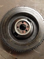
Below are pics from TM Tractor, of the governor gear and the idler gear.
The timing mark on the governor gear is on the edge of the tooth, on the left of the pic.

The timing mark for the governor gear is on the rear side of the idler gear. Look closely. It is on the right in the pic of the gear below. It should be shown in the manual.
 

Attachments

  • Cub idler gear.jpg
    Cub idler gear.jpg
    52.5 KB · Views: 549
  • Cub gov gear 2.jpg
    Cub gov gear 2.jpg
    27.1 KB · Views: 549
After inspecting the crankshaft pulley, I decided to install a new wear sleeve,
49 Crank wear sleeve.jpg

using my new sleeve installation tool.:idea:

Hammer Time sleeve.jpg
(Roller type throw out bearing I decided not to use after reading many negative reviews). Worked perfectly!

Thanks to Glens' timely advice regarding the front cover, I loosened the bolts shortly after tightening them, and installed the pulley. I found it difficult to get the cover/seal aligned just right due to gravity, so I turned the engine like this,
49 Pulley Install.jpg

This position allows the seal on the front cover to center itself around the pulley sleeve without any undue stresses, especially after rotating the crank shaft back and forth a few times. The cover can then be tightened.

As far as the pulley's final position, how far does the pulley need to go? Until it hits the crankshaft gear? There is currently about 1/8" gap between pulley and gear. The oil seal is riding about the same location as the original two grooves were, of course underneath the sleeve. Edit: The oil seal is now 1/4" closer to the pulley than the original groove closest to the pulley. Those 2 grooves look awful close to the tapered part of the pulley.
 
Hi,
yes, the pulley should go on all the way, until it hits the gear, then the fan belt should run straight in line with the upper pulley.

Put some motor oil on the rubber part of new seals, so they have lubrication. :)
 
Crankshaft pulley is on all the way and the oil seal is running on a nice clean surface, barely.
Wear sleeve install.jpg
Is this going to be a problem? I noticed two lips on the seal. The rear lip is good but the front lip is riding on the sleeve with not much room to spare. I could not get the wear sleeve on any further without risking possible damage.


I replaced the needle bearing in governor and have a question about the oil seal.

The original seal had a spring in it and the new one does not. Should I reuse the spring in the new seal?
 
Hi,
If you have an oil seal with 2 lips, the front lip was originally made to keep dirt out of the seal. The rear lip is the oil seal.
As long as the front lip is on the sleeve, it should work, it is not as important as the rear lip.
Several of the original seals on Cubs had the 2 lips, many of the new seals have 1 lip.

I would use the new seal for the governor the way it came.
The engine looks good in the pics. :)
 
In rebuilding the governor, I replaced the internals with one that came off a newer model (same weight), because the original weights opened up so far they were making contact with the housing.

49 Governor.jpg

You can clearly see the wear on the outside of the weights and there was a distinct pattern mark on the inside of the housing where it was making contact...forgot to photo. Can this governor be re built?

49 Governor 2.jpg
 
Tim, I would suspect that either the pins through the weights are worn and grooved, and/or the holes are wallered out. You'll need to take it apart and see where the problem is.
 
Thanks Bob. I took the governor apart and believe it is a case of wallered out holes.
Wallered out governor.jpg

The pins have no grooves and the weights are relatively tight on the pins. I will set this one aside and use it for parts in the future.
 
Got the top and front of the block buttoned up,

49 Block Assembly.jpg

Now its time for the back side (flywheel, clutch and torque tube installation).

It looks like the ring gear needs to be reversed on the flywheel before installing,

49 Flywheel.jpg

I remember Stan in LA telling me a while back that the ring gear can be removed simply by heating with a torch.

Any other tips on removing?
 
Set it up on some wooden blocks so you can knock it off. Face the ring gear down cause it will be hot. It's pretty simple but can be a bear to get started back on. Be gentle and patient. I reversed both of ours and haven't had any issues with either.
 
rockfarmer":1rjqpgc9 said:
It looks like the ring gear needs to be reversed on the flywheel before installing, . . .
Hard to say from just a picture, but it doesn't look that bad to me.
 
I certainly don't want to reverse, if not needed.

Here is picture of the worst spot on the flywheel.

Flywheel 49.jpg

I would much rather hit it with a file for a little while, if that would suffice.
 
It looks like it's already been turned once. The opposite side should look new. Here's the before and after of Arnold.
 

Attachments

  • IMG_6018.JPG
    IMG_6018.JPG
    96.1 KB · Views: 532
  • IMG_6010.jpg
    IMG_6010.jpg
    120.2 KB · Views: 532
Back
Top