Magneto with external coil

Clubless

Well-known member
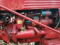
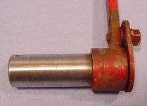
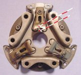
Couple questions about the below ignition setup.
(This is not a picture of my tractor but one I saw in a thread on the forum)

Does the magneto still generate its own power to run engine or does it rely on battery? Does the wire with yellow connectors attach to positive or negative terminal on coil? Would coil be 12 or 6 volt?

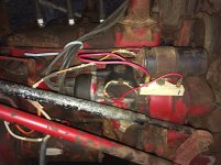
I have non-running Cub that was converted to 12 volt at some point. It has 12 volt battery, 2 prong ignition switch, magneto (internal coil removed), external coil with ballast resistor and non-working alternator.

The coil is a Bosch, but I do not know if it is good or not. There are no marking as to which post is +/- or 12v or 6 volt. I’m thinking of buying a NAPA 12v coil with internal resistor so I can eliminate the external resistor and know I have working coil.

I am not concerned with a charging system or lights, just want to get fire to plugs. I have replaced points, condensor, distributor cap and rotor. I have new copper plug wires and spark plugs.

Not too optimistic about this cub running as it has very low compression. I have not removed head to see how bad it is. Probably will end up as a parts tractor.

Gary
Pilot Mountain NC
 

Attachments

  • 8B469EC6-9A3E-4C87-8279-361CD967DFDD.jpeg
    8B469EC6-9A3E-4C87-8279-361CD967DFDD.jpeg
    36.6 KB · Views: 3,616
Hi,
The magneto in the pic is modified to work about like a Battery Ignition unit, so it is not using it's built in coil.
The ignition wire from it's coil is not connected, the wire is connected to the battery powered coil, so it needs a battery to power the coil.

The small wire from the coil to the magneto could be connected to either post on the coil, depending if the Cub is positive or negative ground. Cubs with 6 volt systems are originally positive ground.
IH changed Cubs to 12 volts, negative ground in 1964.
Some people change 6 volt Cubs to 12 volt negative ground systems.

The Cub in the pic could be 6 or 12 volts.
 
Don't purchase any parts or change anything in the ignition circuit until you find the problem.

Voltage check. Remove the wire from the side of the magneto. Ignition switch on, check for battery voltage on the wire you removed from the magneto. No voltage, start working your way back to the ignition switch checking for voltage at each terminal.

Spark from coil. If you have voltage at the end of the wire you removed from the magneto, remove the magneto coil wire from the coil. Lay the end of the magneto wire about 1/4 inch from the engine block. Ignition switch on, touch and remove the end of the wire you removed from the magneto. If the coil is good, you will have a spark from the magneto coil wire to the engine block.

Some coils use the coil case as a ground for the coil's secondary winding. These coils can be wired in either direction.
 
Eugene...I checked
voltage at battery got 12.4v
switch had 11.8v
wire from switch to one side of coil 11.6v
wire from other side of coil had 6.3v going to one side of ballast resistor
other side of resistor had no voltage which is connected to magneto terminal.

Checked the resistor connectors for continuity and it was good.

Below is picture of my Cub and how it is wired. The orange color wire is from the ignition switch to coil and had 11.6v at the terminal. The red wire coming from near side of coil is connected to left side of resistor and has 6.3v, the other red wire coming from right side of resistor is connected to the magneto terminal and has no voltage.

Thanks guys for responding to questions!
Gary
 

Attachments

  • wiring mag_coil_1.jpg
    wiring mag_coil_1.jpg
    181.4 KB · Views: 3,495
Based on what you checked, it looks like you have an internal resistor coil so I think you can eliminate the resistor. That should allow you to have 6v to the terminal on the side of the mag and your points should fire if there is no other problems.
 
I will remove resistor and attach coil wire to mag tomorrow, then check voltage at the points.

In my first post I commented there were no markings on the coil, but today while mounting the coil I noticed the number 15 near one terminal and the number 4 near the other terminal. Could these numbers indicate the coil has internal resistor?

Now that I have mounted the coil temporarily further away from distributor cap the coil wire is to short. Can I buy a longer one at parts store?
 
Clubless":etn8sz46 said:
In my first post I commented there were no markings on the coil, but today while mounting the coil I noticed the number 15 near one terminal and the number 4 near the other terminal. Could these numbers indicate the coil has internal resistor?
DIN terminal markings. 1 connects to the distributor, 15 (look for it) hot from ignition switch, 4 high voltage to the distributor. That leaves you with the question of whether the coil is for positive or negative ground. Doesn't tell you if it requires a ballast resistor or not.
 
Progress update.

I worked back through the spark/coil issue and now have spark at plugs. Since I’m using 12 volt battery I left the ballast resistor in line. Never did determine which side of coil was positive or negative, so I connected wire from battery to one side of coil and the other coil terminal to ballast resistor and on to mag/distributor terminal.

I replaced spark-plugs, points (.013) and condenser. Put on new copper plug wires and distributor cap. I thought I would be replacing rotor button, but discovered the new “distributor” rotor button will not work on a magneto so the old rotor button stays in place for now. Not sure if I have it in time, but I do have spark.

Drained oil from engine, but when I removed the cap to drain oil filter housing no oil came out. Removed filter and then put filter bolt back in and filled with kerosene. Still no flow, so I used some 10 gauge wire to run through bottom of housing and out the drain pipe. This cleaned out the “sludge”. Filled with 3 qts. of oil and primed oil pump.

Connected up pony tank to rebuilt (but untested) carburetor and fully charged battery.

Turned on gas, pulled out switch and gave starter lever a tug. Got a couple puffs of white smoke but no joy. Decided to check timing. I took valve cover off and rotated engine with fan until #1 and #4 valves were closed, looked for notch on front pulley (which was really close to pointer) and lined up to pointer. Then pulled distributor cap to see position of rotor button, repositioned rotor to point to #1 tower of distributor cap. (Side note: Most threads I have read on timing indicate that the #1 tower is at 1:00 o’clock, mine is at 12:00 o’clock. I do have the tab at bottom of cap seated in the slot at bottom of distributor.)

Pulled on starter lever, squirted a little splash of starter fluid in carburetor and got couple more puffs of smoke. Repeated several times and finally engine started and ran long enough to show oil pressure on gauge. It probably was running on 2 cylinders as it had (has) 2 stuck exhaust valves. Tried to crank a couple more times but battery was getting weak, so I decided to call it a day and declare a small “victory”. Put battery on charger to get ready for round 2.

Sorry for the long post. :tractor:

Gary
 
Hi,
Coils are usually marked near the connections for positive or negative.

The number 1 spark plug terminal on a magneto cap is supposed to be at the top.
1, 3, 4, 2, is the firing order, going clockwise around the cap.
Below is a page from the Cub owner's manual showing the cap position.

http://farmallcub.com/rudi_cub/www.clea ... e%2038.jpg

The cap is turned differently on a Battery Ignition unit. The number 1 terminal is about at 2 oclock, in the Cub owner's manual pic.

http://farmallcub.com/rudi_cub/www.clea ... e%2041.jpg

Yes, a magneto uses a different rotor than a Battery Ignition unit. The rotor has a gear made on the lower part of it. Below is a listing at TM Tractor.

http://www.tmtractor.com/new/el/294fp.htm

The rotor gear area under the cover held on with 2 screws needs cleaning, and the gears greased also, if you didn't see it in the owner's manual.
There are timing marks there for the 2 gears also, that should be aligned.
Below is a pic of under the cover. :)
 

Attachments

  • Cub magneto 4.jpg
    Cub magneto 4.jpg
    25.1 KB · Views: 3,315
Success!

Hooked up freshly charged battery, turned on gas, pulled out switch and tugged on starter lever and she started right up. :tractor: Let it run for a few minutes and then shut it off. Sounds like it is running on 4 cylinders, but not sure. Put 4 ozs of MMO in 1 gallon pony tank and oil. Cranked back up and run for few minutes. Hope I didn’t over do it with MMO.

Checked hydraulics while running and was surprised they worked. Checked fluid level by sticking finger in fill hole, level was good and fluid looked good, not milky.

Still a lot of work to do on this Cub, but I am making progress. Not sure what next step is, probably do another compression test to see if any of the cylinders picked up any compression. Going to have to work on steering before doing a test drive. Tie rods bent and I unhooked them last year to free up steering box. Not sure if I have shims back in correctly. I ‘ll have to read some related threads. Also at some point I will need to determine condition of clutch and transmission. I have not drained transmission fluid at this time but may going ahead and drain and fill with kerosene and take transmission cover off and spray everything down with PB blaster or equivalent.

Are we having fun yet? You bet! :{_}:

Gary
 
Hi,
Good that you got the Cub to run.

Be sure to check the Touch Control fluid level with the arms in the rear, or down position.
The fluid rises in the unit as the arms go to the rear. If you fill it with the arms ahead, it will be overfilled.
The Cubs came with a sticker on the hood for years, that said to check the fluid with the arms in the rear position. Below is a pic from TM Tractor of the sticker.
The owner's manual says it also, at the end of the changing the fluid instructions. :)
 

Attachments

  • Cub decal.jpg
    Cub decal.jpg
    20.6 KB · Views: 3,223
Made some more progress today on the Cub. Found great step by step instructions on YT site on how to convert to 12 volt charging system using Delco 10SI alternator. (Instructions would be great in our “how to” section)

Shortly after bringing this non-running Cub home I removed alternator and had it tested at local parts store and was told it was bad. After reading a number of threads on 12v conversion that showed pictures of Delco 10SI, I was able to determine my “bad” alternator was a Delco 10SI. So, with my step by step instructions in hand I remounted the alternator using the PO’s cobbled up method. It’s not pretty and pulleys don’t line up but I was able to get enough tension to turn alternator and belt stayed on when I cranked engine.

I installed a cheap +30/-30 ammeter and a plastic toggle switch (in lieu of warning light) in dash and started following wiring instructions. After I finished wiring, I pulled out ignition switch, ammeter showed negative charge, and I didn’t smell any electrical smoke. Then I started up engine, looked at ammeter showing discharge, then flipped up toggle switch and ammeter jumped over to charge. I throttled up a little bit and ammeter moved close to 30 amps.

Next, I moved on to possible clutch issues. Clutch pedal has more resistance when pushing down than my other Cubs and grinding when trying to put in gear. Got down under tractor to remove inspection cover (which is missing) to see what things looked like. I was able to reach up and pull down clutch pedal and observed TOB move out to pressure plate. Exited from under tractor and started up tractor and returned to beneath tractor to observe things. Clutch was spinning and thought better of laying under a running tractor, got up and shut down tractor.

Decided to hop up on seat and start up tractor in 2nd gear with clutch depressed. To my surprise the clutch worked and I was able to ease out clutch and move out of and back into shed.

While on clutch discussion, what are some things I could/should do to lubricate parts? I guess putting grease gun on TOB zerk would be helpful. Should I spray PB on clutch fingers and springs and shaft behind TOB?

The next issue to address is the shifter as it needs to be replaced. I will place WTB ad on the Vine for shifter, inspection cover and tie rods.

Side-note: The reason I’m using cheap parts and whatever I have lying around is because I am still unsure if this tractor is anything more than parts unit.

:tractor:

Gary
 
Here is wiring diagram I used to wire up the alternator, ammeter and switch (to excite the alternator).

One difference that I have is the ballast resistor is between coil and distributor instead of between switch and coil. That’s where the PO had it. I assuming it’s a 12v coil.

Also have a question about how I have the coil mounted. I have it pointed straight down just above the distributor cap. Does a coil care which way it points?

:thanx:
Gary
 

Attachments

  • C92EDB45-6900-4F6B-A15C-8D2EFEC8CCC6.gif
    C92EDB45-6900-4F6B-A15C-8D2EFEC8CCC6.gif
    23.1 KB · Views: 703
Hi,
good that you got the Cub to run and alternator to charge.

You should check the clutch pedal free play. It should be 1", for Cubs serial number 32229 and above, with the external adjustment. It is measured at the surface where you put your foot.
If the pedal works hard, it might need lubing at the base, where it goes into the clutch housing. They can get tight from sitting. Keep working penetrating oil into the pedal base. Usually the pedal base will pull out of the housing about 1/4", this helps to work lube into it. Push it back in when done.
If it loosens, oil it with motor oil.

The clutch pressure plate fingers may be too low, a sort of common problem on Cubs. If they are too low, the clutch may not release all the way, then it won't shift without grinding.
Also if the fingers are too low, the metal part of the bearing and the bearing holder can hit on the pressure plate parts, making a grinding noise. Do not push the pedal far enough for the noise to happen, it can damage the parts.

The graphite sticks out of the metal part of a new throwout bearing 5/16", they can wear down from use. If it is worn too low, that can cause problems with it releasing correctly.
They have said on here to lube the throwout bearing grease fitting with cheap grease, so the oil in the grease will absorb into the graphite. The original bearings have a small hole on top, for excess grease to come out.
I put a thin layer of grease on the front of the bearing also, that contacts the fingers.

You could use the spray lube on the finger pivot pins.

Below is a page from the 1950 Cub owner's manual showing adjusting the clutch pedal free play, and a pic of the clutch.

http://farmallcub.com/rudi_cub/www.clea ... e%2040.jpg

Below is a post about setting the height of the pressure plate fingers.

viewtopic.php?f=141&t=66543

Below is a pic from TM Tractor of the pedal base. About 2/3 of the length of the shiny part makes contact in the hole made in the clutch housing. So it needs some oil to get in that far. :)
 

Attachments

  • Cub clutch pedal.jpg
    Cub clutch pedal.jpg
    29.2 KB · Views: 691
Glen

Also have a question about how I have the coil mounted. I have it pointed straight down just above the distributor cap. Does a coil care which way it points?

:thanx:
Gary
 
Clubless":2avx0k3k said:
Also have a question about how I have the coil mounted. I have it pointed straight down just above the distributor cap. Does a coil care which way it points?
No
 
Hi,
It doesn't matter which direction a coil is facing, like Eugene said above.

Below is a pic of a new throwout bearing, the material sticks out of it 5/16", when they get worn down to near the metal, they need replacing.

The 2nd pic shows where to measure when setting the pressure plate finger height. It is measured with the plate assembled on the flywheel. :)
 

Attachments

  • Cub clutch 3.jpg
    Cub clutch 3.jpg
    31 KB · Views: 622
  • Cub 2.jpg
    Cub 2.jpg
    65.8 KB · Views: 622
Back
Top