You are using an out of date browser. It may not display this or other websites correctly.
You should upgrade or use an alternative browser.
You should upgrade or use an alternative browser.
Magneto with external coil
- Thread starter Clubless
- Start date
Hi,
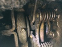
It looks like the throwout bearing is good in your pic.
It looks like one finger is lower than the other in the pic, but hard to tell, sometimes pics don't show exactly.
I would check the finger height.
The fingers should be the same height, so the throwout bearing has a flat surface to push on.
Be sure to lube the bearing, they should not be dry of lube.
When you adjust the fingers, you can loosen the bolt on the clutch pedal adjustment, turn the adjustment, and move the throwout bearing back, so there is more room between the bearing and pressure plate for working.
Measure the pedal free play first, so you know if it was right.
You have to set the free play after done working, if you moved the bearing back.")
It looks like the throwout bearing is good in your pic.
It looks like one finger is lower than the other in the pic, but hard to tell, sometimes pics don't show exactly.
I would check the finger height.
The fingers should be the same height, so the throwout bearing has a flat surface to push on.
Be sure to lube the bearing, they should not be dry of lube.
When you adjust the fingers, you can loosen the bolt on the clutch pedal adjustment, turn the adjustment, and move the throwout bearing back, so there is more room between the bearing and pressure plate for working.
Measure the pedal free play first, so you know if it was right.
You have to set the free play after done working, if you moved the bearing back.
"One difference that I have is the ballast resistor is between coil and distributor instead of between switch and coil. That’s where the PO had it. I assuming it’s a 12v coil"
The ballast resister should be on the wire supplying current to the coil. Although it is running, the resister is having the same effect as points with a little bit of resistance.
My 2 cents
Ron
The ballast resister should be on the wire supplying current to the coil. Although it is running, the resister is having the same effect as points with a little bit of resistance.
My 2 cents
Ron
It doesn't make any difference which resistor comes first in a simple series circuit. The ignition coil primary winding and the ballast resistor are wired in series. The voltage drop is cumulative meaning that the voltage drop across the resistors are added together to obtain the total voltage drop.RonT":3qmdwr2x said:The ballast resister should be on the wire supplying current to the coil. Although it is running, the resister is having the same effect as points with a little bit of resistance.
With regard to ballast resister placement:
Actually, it does make a difference. The ignition coil relies on a oscillating voltage between the coil and condenser after the primary current is interrupted by the points opening. When working properly, the voltage builds up to the point where it will arc across the plug gap. Placing the resister in this portion of the circuit could cause the spark voltage potential to be limited.
Actually, it does make a difference. The ignition coil relies on a oscillating voltage between the coil and condenser after the primary current is interrupted by the points opening. When working properly, the voltage builds up to the point where it will arc across the plug gap. Placing the resister in this portion of the circuit could cause the spark voltage potential to be limited.
Place the ballast resistor in front of the coil if it makes you feel better.
https://www.bing.com/images/search?q=Se ... ORM=IDINTS
Check out the above link. Notice that voltage oscillations between the coil and condenser occur after the spark plug has fired. Also note that there is some minor ripples in the coil's circuits as the coil saturates after the points close. Once the coil is saturated, the circuits flat line until the point open and the plug fires.
Clubless
Well-known member
Hi all,
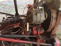
Got a couple of updates on the Cub regarding coil and new compression readings.
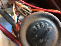
First the coil, since I have it mounted pointing straight down I noticed some marking on the bottom of coil (had not looked there before). The marking is TE6B4. A quick Goggle search offered up information that the coil is 6v used in VW's & Porsche ignition systems. I never imagined the ole tractor had some Porsche in it :lol:. Does this new information impact where the ballast resister is located? The tractor is 12v with alternator.
When I first checked compression (before I had it running) the readings were 90,0,0,30 (dry) and 180,30,30,90 (wet). Since I have been running engine for 10-15 minute durations on a number of occasions, I wanted to see if compression had improved. Dry tested today with the following readings; 120,118,85,120. Put a squirt or two of oil in #3 and it came up to 90. I was really pleased with readings, although I would like #3 to be more in line with the other cylinders.
:thanx:
Gary :tractor:
Got a couple of updates on the Cub regarding coil and new compression readings.
First the coil, since I have it mounted pointing straight down I noticed some marking on the bottom of coil (had not looked there before). The marking is TE6B4. A quick Goggle search offered up information that the coil is 6v used in VW's & Porsche ignition systems. I never imagined the ole tractor had some Porsche in it :lol:. Does this new information impact where the ballast resister is located? The tractor is 12v with alternator.
When I first checked compression (before I had it running) the readings were 90,0,0,30 (dry) and 180,30,30,90 (wet). Since I have been running engine for 10-15 minute durations on a number of occasions, I wanted to see if compression had improved. Dry tested today with the following readings; 120,118,85,120. Put a squirt or two of oil in #3 and it came up to 90. I was really pleased with readings, although I would like #3 to be more in line with the other cylinders.
:thanx:
Gary :tractor:
Attachments
No.Clubless":2moziur9 said:Does this new information impact where the ballast resister is located?
I would add SeaFoam to the oil and gasoline. Operate the engine/tractor for a considerable length of time, something like 30 or 40 hours, then again check the compression.
We used the points in the magneto or stator-with the external coil when the coils failed. Beaware of the ballast resistor, and the full 12v for starting only then it runs off the resistor. There’s a extra wire we run from the solenoid to the coil. If it’s not correct the points will burn.
Personally I like magnetos there rock solid dependable when there right. I worked on wico, to Fairbanks mags to older Edison mags. I brought the dead back to life.
Inside the mag there’s a drum that has a spring wind up. A lever comes out to let the spring wind up on the drum then it snaps free to create more wattage when starting. Make sure the wind up lever is free. Most of the problems I seen with this setup the lever is stuck. Check to see if your magneto has this design.