Compression Wave Form with Oscilloscope

Short stroke or long stroke, long duration or short duration. It doesn’t take mass or the human factor out of the equation. I didn’t mean to ruffle any feathers. If I did please forgive me.
 
I find this discussion very interesting. At some point can you share specs and source for the tools so someone with interest can duplicate the tests?
 
phill_mi":6j2p8foi said:
I find this discussion very interesting. At some point can you share specs and source for the tools so someone with interest can duplicate the tests?
First let me say this equipment is typically not cheap, but you can cut some corners and save money. The automotive shops that do this type testing have pretty sophisticated equipment and analyzers with on screen capability for viewing the oscilloscope tracing in real time. I believe most folks that have their own personal equipment typically use what is called an automotive pico-scope. I have my own equipment which I have owned for about fifteen years and until now only used it for work related activities. So I really cannot comment on the pico-scope and how well they perform. I think they can be purchased for about $250 if you only need a couple of channel inputs.

This is a description of the equipment I used. There are only three (3) main pieces of equipment and some minor hardware/cable/connectors.

1. Transducer: this sensor threads into the spark plug opening and measures the pressure inside the cylinder. It converts the pressure into an analog voltage signal that is proportional to the pressure. I recently purchased the transducer, and I went low dollar because most of the compound transducers on the market are quite expensive. I purchased this online from Transducers Direct and they manufacture their own sensors. This one cost about $150 and the cable connector mentioned below was $20. The pressure range is -14.7 to 150 psig, 0-10 Vdc output, 24 Vdc power supply, 0,25% accuracy, ¼” NPT process connection. The part #TDH43DGV15003B002

2. Data Acquisition Hardware with software: This is the brains of the system. It is a basically an analog to digital converter smthat accepts the sensor inputs and utilizes the software to graphically display the information in a variety of ways to suit the application. It is USB based so the output can be stored and displayed on a computer. The unit I have has 8 channels for 8 analog inputs and also 8 digital input/outputs. Back in 2008 this unit along with the software was $600. The manufacturer is Measurement Computing Corporation and the model #USB-1608FS. The software isTracerDAQPro.

3. Power Supply: The transducer and the data acquisition module both require excitation power to operate. The power supply I have uses 110 Vac input and provides up to 24 or 48 Vdc power output at varying amperage. The power supply module is manufactured by Omega, Part #U24Y101 and back in 2008 was $169. You will also need a 110 Vac power input cable with 3-conductor pigtail ends (I made my own).

Additionally, the transducer requires an adapter to thread into the spark plug opening. So it is basically a bushing with male threads that fit into the 18 mm spark plug opening and ¼” NPT female threads to accept the transducer. I use an air-hold-fittings set that you can purchase from NAPA for about $12. Finally, you will need a cable connector assembly to connect the transducer to the power supply and Data Acquisition module. I used a Packard 3-pin connector with 3m long 3-conductor cable and flying ends. This is the $20 I mentioned above. If you have any questions, let me know.
 
UPDATE: I liked Jim Becker’s suggestion to conduct a running compression test. It makes sense that at engine idling speeds the valve timing should be more representative of normal operation. To make this test as comparable as possible to the cranking pressure test, Cylinder #1 was used, and the engine warmed up prior to the test. After warm-up, I removed the spark plug and installed the transducer. To give the spark somewhere to go, I installed a spark tester to the spark plug wire and grounded it to the engine. Obviously, there is no way to prevent fuel from entering the #1 Cylinder, but the test should last about 20 seconds so that should not cause any problems.

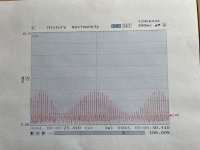
After recording the waveform a quick observation demonstrated what I was hoping to see regarding pressure and vacuum readings and durations during the exhaust and intake strokes. However, a closer inspection revealed non-uniform compression at TDC. When I enlarged the time frame of the tracing, I was shocked at the appearance of the waveform. Sorry I didn't take time to add notes to the chart, but each of the peaks represents TDC Compression with the highest readings are about 45 psig. Also the lowest pressures during intake stroke were much closer to full vacuum compared to the cranking test.

IMG_6360.jpg

I wanted to believe there wasn’t a problem and there must be a logical explanation. Especially considering that the peak pressure waveform resembles a bell curve that has a predictable cycle of approximately 2 seconds. I think this is not representative of a mechanical or electrical problem but something unexpected that is going to require a little more reasoning.

The only difference between the cranking test versus the running pressure tests are 1) higher engine rpm’s during the running test, 2) that fuel is introduced into #1 cylinder during the running test and 3) during the running test the other three cylinders are operating and producing ignition, power and exhaust. Fuel enters #1 cylinder and is not ignited, so no power is produced. Air entering the cylinder is compressible, but fuel is not. This creates non-uniform pressure cycles as some fuel evaporates and some may be forced out the exhaust, while some remains as a liquid. This creates a pressure imbalance. The other condition is that there is likely a speed imbalance with Cylinder 1. One cylinder is misfiring, while the other cylinders are firing normally.

I had expected lower peak pressure during the running compression test, but the peak pressures on the oscilloscope were lower than expected. So I removed the transducer and conducted a running pressure test using a compression gauge. Both the gauge and transducer had similar readings of 40-45 psig, so no issue with the pressure sensor.
In any event that’s my story until someone comes up with a more logical explanation. Although the results were unforeseen, maybe it is a learning experience.
 
During the test, was the engine speed being controlled by the governor? If so, it may have been cycling the throttle. I am guessing it could be moving the throttle enough to show up in the readings even if so slight that there was no audible speed variation. If this seems like a possibility and you want to chase it any more, there are a couple things you could try:
1) Move your sensor to the intake manifold and see if there is a cycle in the vacuum with the engine running at the previous test speed.
or
2) Repeat the running test setting the idle adjust screw to obtain the test speed, keeping the governor control at the slow idle position. This would take the governor out of the picture.
 
Spark or not the fuel will be warm from the warm engine intake and the heat of compression will raise the temp in the cylinder and should vaporize most of the fuel as in a normal cycle even if the cylinder is not quite as hot from no spark/ignition burn from the previous cycle. The question would be during the expansion stroke if the fuel stays in vapor form or condenses before it is exhausted.

I wonder if the heat of the engine and from compression is somehow compromising the seal of the transducer and the mechanical gauge to the spark plug hole only allowing you to build up to 45 psi. ??
 
Not trying to beat you up about it.
Just curious, but what is the reason for all this?
What is the goal?

In a past life, I installed lots of pressure transducers in plastic injestion molds for process control at the request of production or the engineering folk.
 
inairam":2npoi4xh said:
I wonder if the heat of the engine and from compression is somehow compromising the seal of the transducer and the mechanical gauge to the spark plug hole only allowing you to build up to 45 psi. ??
The engine was idling, no load. Under these conditions, even if idling at 1,800 rpm, the throttle is mostly closed to keep the engine from over-reving. This puts the intake manifold at high vacuum and limits the amount of air/fuel taken in at each intake stroke. The lower amount taken in reduces the compression reading accordingly. If you were to attach the engine to a full load so the throttle was wide open, you would see higher compression readings.
 
Jim Becker":13iwm0f1 said:
During the test, was the engine speed being controlled by the governor? If so, it may have been cycling the throttle. I am guessing it could be moving the throttle enough to show up in the readings even if so slight that there was no audible speed variation. If this seems like a possibility and you want to chase it any more, there are a couple things you could try:
1) Move your sensor to the intake manifold and see if there is a cycle in the vacuum with the engine running at the previous test speed.
or
2) Repeat the running test setting the idle adjust screw to obtain the test speed, keeping the governor control at the slow idle position. This would take the governor out of the picture.

During the test I set the throttle at idle and then measured engine speed with a Stuart Warner hand held tachometer. It was approximately 1400 rpm. However, that was based on running on all 4 cylinders. When I started the tractor on three cylinders, and at the same throttle setting, I really could not detect any difference by sound. The engine seemed to be running at a constant rpm, although I did not measure it on three cylinders.

I ran two tests on three cylinders and the waveform was consistent on both tests. The average time duration between compression pressure peaks was 75 milliseconds with the highest duration of 80 msec and the lowest of 70 msec. And there was no pattern to suggest the highest duration occurred at the lowest pressure peaks or vice versa. Knowing that the crank rotates two times between compression peaks that translates into an average engine speed of 1600 rpm and with a low of 1500 and a high of 1714 rpm. That surprised me because I could not detect any significant difference in the sound of the engine running on three versus 4 cylinders. I do plan to install the pressure transducer on the intake manifold, but need a different adapter fitting that I have on order.
 
inairam":16x8hrwl said:
Spark or not the fuel will be warm from the warm engine intake and the heat of compression will raise the temp in the cylinder and should vaporize most of the fuel as in a normal cycle even if the cylinder is not quite as hot from no spark/ignition burn from the previous cycle. The question would be during the expansion stroke if the fuel stays in vapor form or condenses before it is exhausted.

I am curious about how much fuel remains in liquid form, because I am a little concerned that the gas could affect the oil's ability to lubricate the cylinder walls. But I only conducted the 3-Cylinder test for about 20 seconds each time, so should not be a problem.

inairam":16x8hrwl said:
I wonder if the heat of the engine and from compression is somehow compromising the seal of the transducer and the mechanical gauge to the spark plug hole only allowing you to build up to 45 psi. ??

I don't think the heat is too high and the time of exposure wasn't long, so I doubt there is any damage, and like Jim Becker noted below, I expected lower peak pressure because the throttle is not wide open as it would be in a cranking pressure test. I had read that the running peak pressure should be about 50% of the cranking peak pressure, so it was a little lower, but I think there is something else going on that I can't get my brain around yet.
 
SamsFarm":3szti5xv said:
Not trying to beat you up about it.
Just curious, but what is the reason for all this?
What is the goal?

Truth be told, I think it is interesting and a learning experience at the same time, especially since I searched high and low on this subject, relative to cubs or any tractors for that matter and found nothing other than compression tests with a gauge.

The goal is to see if there is anything that I can do to fine tune the engine and duplicate the kind of wave forms I expected to see. Still trying to understand if this is possible. The other goal is to keep the brain working in old age.
 
Back
Top