I moved my IH loader from a Cub with no TC to a 130 with a TC. The IH loader was modified by the previous owner with a double-acting boom cylinder and a different directional control valve and a filter on the out port and a pump from a numbered cub with hose fittings. The loader worked great for 5 years on the club with this setup.
On the Cub without a TC is was simple: pump to valve out to filter and reservoir back to the pump.
With the touch control and bypass block its a two-circuit system of course and because the valve is not standard the manual is not clear to me as to how to plumb it.
The valve I have has a pressure beyond port and an out port. The out port is plumbed to the filter then to the reservoir. The beyond port is plugged.
Should I tap the pressure beyond the port run a hose to return to the bypass block?
The manual shows an overflow hose from the loader reservoir to the fill plug on the TC. Is that needed?
This site uses cookies to maintain login information on FarmallCub.Com. Click the X in the banner upper right corner to close this notice. For more information on our privacy policy, visit this link: Privacy Policy
NEW REGISTERED MEMBERS: Be sure to check your SPAM/JUNK folders for the activation email.
Hydrolics experts help - IH1000 loader - non standard valve
Forum rules
Notice: For sale and wanted posts are not allowed in this forum. Please use our free classifieds or one of our site sponsors for your tractor and parts needs.
Notice: For sale and wanted posts are not allowed in this forum. Please use our free classifieds or one of our site sponsors for your tractor and parts needs.
-
inairam
- 5+ Years

- Posts: 2834
- Joined: Wed Jul 08, 2015 10:24 am
- Zip Code: 19342
- Tractors Owned: 1948 6v - Dozer
1949 with kub klipper belly mower. mag 6v - Mom
1950 with plow, 54 blade, mott mag 6v - Roxanne
1953 54 blade, c22, wood 42 6v
1957 6v - barn Queen
1965 lo-boy with c-3 mower 12 v - Loboy
1974 Horse II 12 v c-2
1975 with woods 42-6 12 v - Horse
1979 long strip 12 v stuck engine
130 with international 1000 loader 6 v
1969 140 with bush hog tow behind mower 12 v
Terramite T-6 4WD Backhoe Perkins diesel
Memberships: Rough and Tumble Engineers Historical Association;Chapter 8 IH Collectors; IH Collectors Worldwide - Circle of Safety: Y
- Location: Glen Mills PA
Hydrolics experts help - IH1000 loader - non standard valve
When you only have 9 horsepower you need to know the names of all of the ponies!
-
Rick Prentice

- Team Cub Guide

- Posts: 5636
- Joined: Mon Nov 01, 2004 7:24 am
- Zip Code: 43528
- Tractors Owned: 47(circle cub),48(Floyd backhoe),49,,51,54 and another 55
- Circle of Safety: Y
- Location: OH, Holland
Re: Hydrolics experts help - IH1000 loader - non standard valve
If I'm understanding your description then Yes, leave the filter plumbing alone IF it dumps directly back into the reservoir, and connect the power beyond into the pressure return port on the bypass block. The only drawback with the filter mounted there is it only filters at a minimum. Under normal running of the tractor the flow will be from pump through the control valve, out the power beyond port back into the bypass pressure inlet port and into the T/C unit and T/C reservoir and back to the pump.
Maybe someone else can explain things easier. Let me rethink things and repost
Rick
Maybe someone else can explain things easier. Let me rethink things and repost
Rick
When I told my dad I've been misplacing things and doing stupid stuff----His reply---"It only gets better"
-
Rick Prentice
- Team Cub Guide
- Posts: 5636
- Joined: Mon Nov 01, 2004 7:24 am
- Zip Code: 43528
- Tractors Owned: 47(circle cub),48(Floyd backhoe),49,,51,54 and another 55
- Circle of Safety: Y
- Location: OH, Holland
Re: Hydrolics experts help - IH1000 loader - non standard valve
Ok. So are you using the 130"s manifold lines from the 130's pump to it's 130 T/C unit? And I'm assuming you're removing the pressure hose that use to run from the old cub pump to the inlet on new control valve, correct?
 TM pic
If so, you'll plumb from the side of manifold lines back to the "IN" on control valve, then I would remove the filter plumbing all together, and run a pressure hose from the "OUT" on control valve to the bypass pressure "IN" port on the bottom of bypass. Leave the power beyond capped off on the control valve, it's not needed because the T?C unit has pressure relief features and you'll never generate enough pressure to blow the side out of that control valve while using the T?C only.
That's my opinion.
Rick
TM picIf so, you'll plumb from the side of manifold lines back to the "IN" on control valve, then I would remove the filter plumbing all together, and run a pressure hose from the "OUT" on control valve to the bypass pressure "IN" port on the bottom of bypass. Leave the power beyond capped off on the control valve, it's not needed because the T?C unit has pressure relief features and you'll never generate enough pressure to blow the side out of that control valve while using the T?C only.
That's my opinion.
Rick
When I told my dad I've been misplacing things and doing stupid stuff----His reply---"It only gets better"
-
Rick Prentice
- Team Cub Guide
- Posts: 5636
- Joined: Mon Nov 01, 2004 7:24 am
- Zip Code: 43528
- Tractors Owned: 47(circle cub),48(Floyd backhoe),49,,51,54 and another 55
- Circle of Safety: Y
- Location: OH, Holland
Re: Hydrolics experts help - IH1000 loader - non standard valve
If you're more comfortable leaving the filter setup in place, plumb that filter hose into the T/C reservoir fitting, then using the power beyond port run a pressure hose from there to the bottom of the bypass block. That will complete the pressure circuit. Hope that's not too confusing.
When I told my dad I've been misplacing things and doing stupid stuff----His reply---"It only gets better"
-
inairam
- 5+ Years
- Posts: 2834
- Joined: Wed Jul 08, 2015 10:24 am
- Zip Code: 19342
- Tractors Owned: 1948 6v - Dozer
1949 with kub klipper belly mower. mag 6v - Mom
1950 with plow, 54 blade, mott mag 6v - Roxanne
1953 54 blade, c22, wood 42 6v
1957 6v - barn Queen
1965 lo-boy with c-3 mower 12 v - Loboy
1974 Horse II 12 v c-2
1975 with woods 42-6 12 v - Horse
1979 long strip 12 v stuck engine
130 with international 1000 loader 6 v
1969 140 with bush hog tow behind mower 12 v
Terramite T-6 4WD Backhoe Perkins diesel
Memberships: Rough and Tumble Engineers Historical Association;Chapter 8 IH Collectors; IH Collectors Worldwide - Circle of Safety: Y
- Location: Glen Mills PA
Re: Hydrolics experts help - IH1000 loader - non standard valve
Rick, If I remove the filter use the out port to connect to the TC bypass there will be nothing going to the reservoir on the loader and so nowhere to receive fluid from the cylinders when they contract. I tried connecting the hose from the filter to the return but it blows the filter seal and I have no TC or loader movement.
The manual shows 3 connections to/ from the valve: one from the small port on the 130 manifold to valve in, one to the reservoir that they call a " sump line" which I assume is low pressure out which In my setup goes to the filter, and one returning to the bypass block.
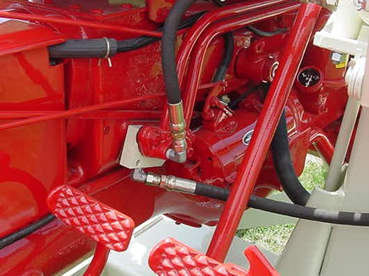
In the manual, there is a 4th line - a low-pressure connection from the loader reservoir to the TC fill plug. that is the large black line in the background of pic you posted.
The two lines I do not have are the high-pressure return to the bypass block and the overflow return to the etc. They is why I thought to use power beyond the port to connect to the bypass block.
The manual shows 3 connections to/ from the valve: one from the small port on the 130 manifold to valve in, one to the reservoir that they call a " sump line" which I assume is low pressure out which In my setup goes to the filter, and one returning to the bypass block.
In the manual, there is a 4th line - a low-pressure connection from the loader reservoir to the TC fill plug. that is the large black line in the background of pic you posted.
The two lines I do not have are the high-pressure return to the bypass block and the overflow return to the etc. They is why I thought to use power beyond the port to connect to the bypass block.
When you only have 9 horsepower you need to know the names of all of the ponies!
-
Rick Prentice
- Team Cub Guide
- Posts: 5636
- Joined: Mon Nov 01, 2004 7:24 am
- Zip Code: 43528
- Tractors Owned: 47(circle cub),48(Floyd backhoe),49,,51,54 and another 55
- Circle of Safety: Y
- Location: OH, Holland
Re: Hydrolics experts help - IH1000 loader - non standard valve
Sorry. I didn't think about your loader having an additional reservoir. I'll have to study the IH 1000 setup.
When I told my dad I've been misplacing things and doing stupid stuff----His reply---"It only gets better"
-
Rick Prentice
- Team Cub Guide
- Posts: 5636
- Joined: Mon Nov 01, 2004 7:24 am
- Zip Code: 43528
- Tractors Owned: 47(circle cub),48(Floyd backhoe),49,,51,54 and another 55
- Circle of Safety: Y
- Location: OH, Holland
Re: Hydrolics experts help - IH1000 loader - non standard valve
So then from the pump back the small manifold line, out the side fitting to the "IN" on control valve, out the power beyond fitting to the bottom pressure fitting on bypass block. That big hose that runs from 1000 loader reservoir to T?C fill plug, you could "T" and plumb your filter hose to it that comes from the "OUT" on the control valve. Those hoses are no pressure, just return lines. Your 1000 loader has a breather on top of the reservoir tank below the control valve. That should be the highest point in the fluid system.
When I told my dad I've been misplacing things and doing stupid stuff----His reply---"It only gets better"
-
Rick Prentice
- Team Cub Guide
- Posts: 5636
- Joined: Mon Nov 01, 2004 7:24 am
- Zip Code: 43528
- Tractors Owned: 47(circle cub),48(Floyd backhoe),49,,51,54 and another 55
- Circle of Safety: Y
- Location: OH, Holland
Re: Hydrolics experts help - IH1000 loader - non standard valve
We need some IH1000 loader guys to chime in.
When I told my dad I've been misplacing things and doing stupid stuff----His reply---"It only gets better"
-
Rick Prentice
- Team Cub Guide
- Posts: 5636
- Joined: Mon Nov 01, 2004 7:24 am
- Zip Code: 43528
- Tractors Owned: 47(circle cub),48(Floyd backhoe),49,,51,54 and another 55
- Circle of Safety: Y
- Location: OH, Holland
Re: Hydrolics experts help - IH1000 loader - non standard valve
Does the loader pedestal reservoir have more than one fitting in the side of it. It looks like in the loader manual there's a steel tube exiting the original control valve bottom( this would act like your "OUT" with filter setup) and plumbed into the pedestal, then another fitting on the pestal that accepts that larger hose to the T?C fill plug. That would keep fluid transferring when using the loader and when only using T?C the fluid would flow normal. If this is true, you'd plumb your "OUT" with filter into that fitting on pedestal where old control valve connected, and just plumb the big hose from side of pedestal to the T?C fill plug. You'd fill the pedestal with fluid leaving room for expansion and that should fill the system everywhere else. The whole system would breath through that breather on the top of pedestal. Sorry for the confusion.
Rick
Rick
When I told my dad I've been misplacing things and doing stupid stuff----His reply---"It only gets better"
-
inairam
- 5+ Years
- Posts: 2834
- Joined: Wed Jul 08, 2015 10:24 am
- Zip Code: 19342
- Tractors Owned: 1948 6v - Dozer
1949 with kub klipper belly mower. mag 6v - Mom
1950 with plow, 54 blade, mott mag 6v - Roxanne
1953 54 blade, c22, wood 42 6v
1957 6v - barn Queen
1965 lo-boy with c-3 mower 12 v - Loboy
1974 Horse II 12 v c-2
1975 with woods 42-6 12 v - Horse
1979 long strip 12 v stuck engine
130 with international 1000 loader 6 v
1969 140 with bush hog tow behind mower 12 v
Terramite T-6 4WD Backhoe Perkins diesel
Memberships: Rough and Tumble Engineers Historical Association;Chapter 8 IH Collectors; IH Collectors Worldwide - Circle of Safety: Y
- Location: Glen Mills PA
Re: Hydrolics experts help - IH1000 loader - non standard valve
The extra ports are there and that is what i.am going to try. I just need some hydrolic hose for the power beyond port.
When you only have 9 horsepower you need to know the names of all of the ponies!
-
Jim Becker
- Team Cub

- Posts: 17301
- Joined: Sun Feb 02, 2003 2:59 pm
- Zip Code: 55319
- Circle of Safety: Y
- Location: MN
Re: Hydrolics experts help - IH1000 loader - non standard valve
OK, I think I can help here. However, there are some points to consider first.
1) I'm not sure what modifications were made to your loader but think I can get through it anyway.
2) I read most of what Rick said and believe it gets you to the right place.
3) I'm not sure how well my comments and Rick's will mix. So either follow all of what Rick said and ignore what I suggest or all of what I said and ignore what Rick suggested. Either may get you to the same place or equivalent places, but don't mix them.
--------------- STOP READING HERE OR NOT ---------------------
The original valve was a power beyond valve. So all you need to do is replicate the original connections. The outlet from the right side of the original valve was a power beyond connection and was connected to the side of the bypass block. The Return outlet came out the bottom of the valve and used a hard line to the left side of the reservoir built into the loader frame. Below the hard line connection to the reservoir is another connection point. A non-pressurized hose from this point ran to the Touch-Control filler plug.
I believe, from pictures you posted earlier, that your low-pressure return currently goes via your filter into the lower left side reservoir point. I couldn't tell if you have anything connected to the upper left point (where the hard line originally went). It looks like it currently has an elbow with a plug. You need to move the filter outlet to the upper left side connection and add a hose from the lower left side connection to the Touch-Control filler.
Your loader valve inlet needs high pressure directly from the Touch-Control system. You do that by connecting from the originally-plugged pressure feed on the Touch-Control manifold to the loader valve inlet. This is the hose that goes mostly straight up in Rick's picture. The power beyond outlet from your loader valve needs to feed the bypass block added to the Touch-Control. This is the hose going out the right side of Rick's picture.
That is all it should take to have a working system. This does leave the filter only filtering oil that returns from the loader cylinders, with all other flow bypassing it. This is still a step up from the original configuration that has no filter. You could probably move the filter to the only other non-pressurized connection in the system, the hose going to the Touch-Control filler. This would filter all the oil going into the pump. It would probably be OK, but filters on the intake side of a pump is generally considered a poor practice. Connecting the filter anywhere else would be on a high pressure line and you already found out that doesn't work.
Do NOT use the return outlet of a power beyond valve to feed pressure into the bypass block of the Touch-Control. Power beyond valves can do some strange and unwanted things if pressure is held on that port.
-
inairam
- 5+ Years
- Posts: 2834
- Joined: Wed Jul 08, 2015 10:24 am
- Zip Code: 19342
- Tractors Owned: 1948 6v - Dozer
1949 with kub klipper belly mower. mag 6v - Mom
1950 with plow, 54 blade, mott mag 6v - Roxanne
1953 54 blade, c22, wood 42 6v
1957 6v - barn Queen
1965 lo-boy with c-3 mower 12 v - Loboy
1974 Horse II 12 v c-2
1975 with woods 42-6 12 v - Horse
1979 long strip 12 v stuck engine
130 with international 1000 loader 6 v
1969 140 with bush hog tow behind mower 12 v
Terramite T-6 4WD Backhoe Perkins diesel
Memberships: Rough and Tumble Engineers Historical Association;Chapter 8 IH Collectors; IH Collectors Worldwide - Circle of Safety: Y
- Location: Glen Mills PA
Re: Hydrolics experts help - IH1000 loader - non standard valve
I got some more hoses and redid the plumbing to match the manual But still have no real pressure. I got limited movement at times on both the TC and loader, lots of bleeding but limited range of motion and no speed.
the flow path I think is as follows:
pump to bypass block
Bypass block to directional control ( bleed point)
power beyond to bypass block/TC inlet
out to filter/ reservoir
reservoir overflow to TC fill.
I can see flow back to the TC fill and I can see fluid and air bubbles at the bleed at direction control valve inlet but the pressure does not appear strong.
Any suggestions?
- Attachments
-
-
-
-
-
When you only have 9 horsepower you need to know the names of all of the ponies!
-
Jim Becker
- Team Cub
- Posts: 17301
- Joined: Sun Feb 02, 2003 2:59 pm
- Zip Code: 55319
- Circle of Safety: Y
- Location: MN
Re: Hydrolics experts help - IH1000 loader - non standard valve
inairam wrote:out to filter/ reservoir
reservoir overflow to TC fill.
What do you mean by "reservoir overflow"? The lower point on the reservoir needs to connect to the Touch-Control filler. Otherwise you are likely to pick up air
-
inairam
- 5+ Years
- Posts: 2834
- Joined: Wed Jul 08, 2015 10:24 am
- Zip Code: 19342
- Tractors Owned: 1948 6v - Dozer
1949 with kub klipper belly mower. mag 6v - Mom
1950 with plow, 54 blade, mott mag 6v - Roxanne
1953 54 blade, c22, wood 42 6v
1957 6v - barn Queen
1965 lo-boy with c-3 mower 12 v - Loboy
1974 Horse II 12 v c-2
1975 with woods 42-6 12 v - Horse
1979 long strip 12 v stuck engine
130 with international 1000 loader 6 v
1969 140 with bush hog tow behind mower 12 v
Terramite T-6 4WD Backhoe Perkins diesel
Memberships: Rough and Tumble Engineers Historical Association;Chapter 8 IH Collectors; IH Collectors Worldwide - Circle of Safety: Y
- Location: Glen Mills PA
Re: Hydrolics experts help - IH1000 loader - non standard valve
Jim I mean the side port on the column that the manual shows going back to the TC fill plug
I think I need power beyond plug to keep the High pressure from bleeding off to the out port. I have no numbers on the valve that I can see to get a model number. I really hate not having manuals on something like a directional control valve.
I think I need power beyond plug to keep the High pressure from bleeding off to the out port. I have no numbers on the valve that I can see to get a model number. I really hate not having manuals on something like a directional control valve.
- Attachments
-
When you only have 9 horsepower you need to know the names of all of the ponies!
-
Rick Prentice
- Team Cub Guide
- Posts: 5636
- Joined: Mon Nov 01, 2004 7:24 am
- Zip Code: 43528
- Tractors Owned: 47(circle cub),48(Floyd backhoe),49,,51,54 and another 55
- Circle of Safety: Y
- Location: OH, Holland
Re: Hydrolics experts help - IH1000 loader - non standard valve
I found this on the Prince website:
Valves: Prince has a few locations where valves will get pin stamped. Prince typically pin stamps the model # and date of manufacture. You will also find casting #’s (C-XXX or HCI-PRINCE) on the valves, so if you are not able to find the pin stamping, this will give you a start in identifying what valve series you have. Please refer to the valve casting # identification section.
Model # Series Where the pin stamp is located
RD-400 Hex plug end cap on controlled flow end
RD-500 Hex plug end cap
RD-900 On non-handle end with ports up, model code on surface directly above spool, date code on surface directly below spool.
RD-1000 On face of adjusting plug
RD-1400 Hex plug end cap
RD-1500 Model No. and Date Code on right end cap, orifice size on left cap (ratio and orifice size of left cap if ratio is not 50:50)
RD-1600 Top of body (same surface as the “IN”, “CYL” & “PP” detail)
RD-1800 Top (Tank port side) of mach body
RD-1900 Hex plug end cap
RDRS-100 Hex plug end cap
RDRS-1900 Hex plug end cap
RD-2500 End plate opposite the handle
RD4100 SERIES End cap opposite the handle
RD5100 SERIES End cap opposite the handle
RD5200 SERIES End cap opposite the handle
RD5300 SERIES End cap opposite the handle
RV On hex flats of relief cartridge
SS On end of valve on machined surface opposite handle end
SV ASSEMBLIES Outer machined face of inlet
SV INLET Outer machined face
SV OUTLET Outer machined face
SV WORK SECTIONS End cap opposite the handle
SVX…-TXXX TANDEM SOLENOID Machined face on side of actuator body nearest the B port
When I told my dad I've been misplacing things and doing stupid stuff----His reply---"It only gets better"
-
- Similar Topics
- Replies
- Views
- Last post
-
-
Front Hydrolics pump Attachment(s)
by inairam » Fri Oct 15, 2021 1:01 pm » in Farmall A, Super A, AV, 100, 130 & 140 - 2
- 176
-
by inairam
Sun Oct 17, 2021 9:01 pm
-
-
-
pressure relief valve c123
by inairam » Fri Sep 17, 2021 5:18 pm » in Farmall A, Super A, AV, 100, 130 & 140 - 3
- 358
-
by rjohnson
Sat Sep 18, 2021 7:39 am
-
-
-
Loader Attachment(s)
by liquid plumber » Mon Oct 25, 2021 9:13 pm » in Farmall A, Super A, AV, 100, 130 & 140 - 11
- 617
-
by inairam
Mon Nov 08, 2021 9:13 am
-
-
-
IH 1000 Loader Attachment Attachment(s)
by ninewaterfalls » Sat Jul 30, 2022 5:14 pm » in Farmall A, Super A, AV, 100, 130 & 140 - 12
- 798
-
by ninewaterfalls
Mon Aug 01, 2022 8:01 am
-
-
-
IHC 1000 Loader (Air in the Lines or something) Attachment(s)
by jmm_spqr@yahoo.com » Mon Dec 19, 2022 9:35 am » in Farmall A, Super A, AV, 100, 130 & 140 - 30
- 554
-
by inairam
Wed Jan 11, 2023 1:29 pm
-
Return to “Farmall A, Super A, AV, 100, 130 & 140”
Who is online
Users browsing this forum: No registered users and 0 guests