Interference issue between tire and grader blade.

Lt.Mike

501 Club
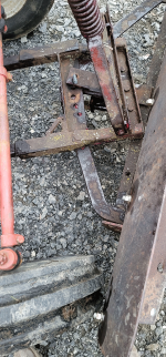
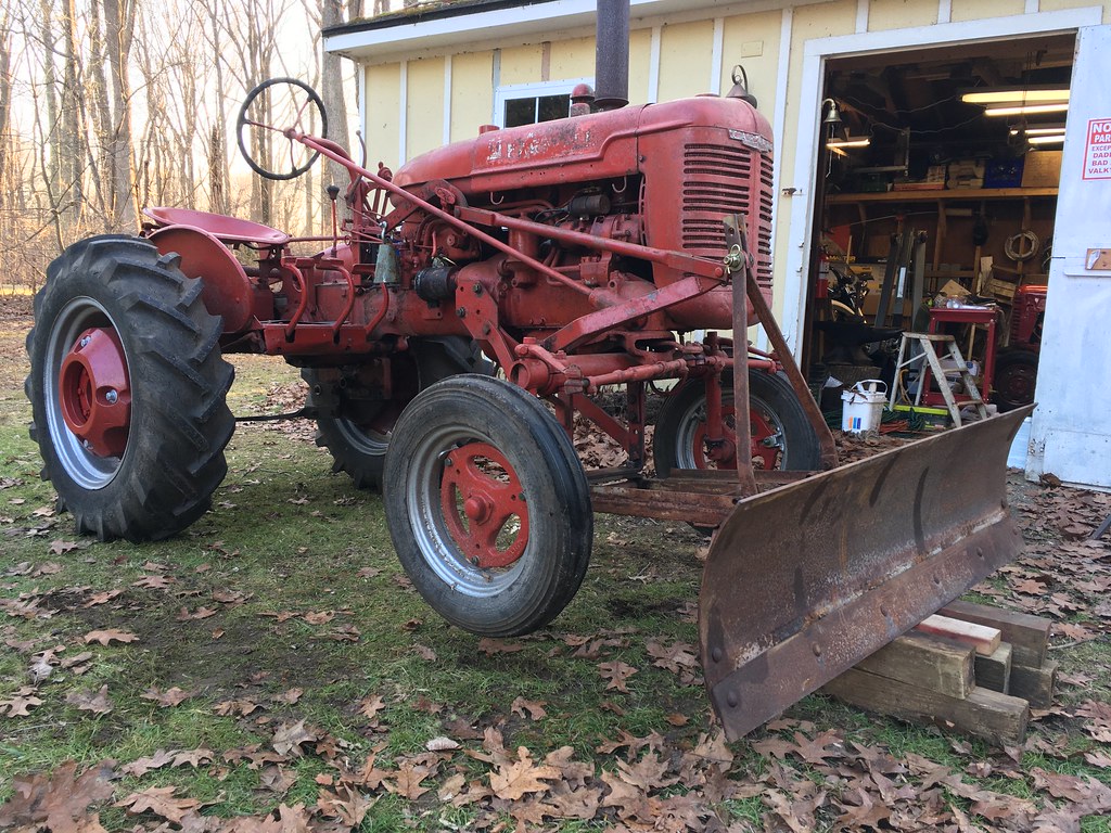
I’m moving forward with power angling the A60 blade I’ve mounted to the front of my SA.
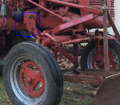
Today I went out to do a couple tractor related things, mounted the weights on Paula’s cub and I decided to pull the SA out of the shed to measure the blade bow to frame from lock to lock, canting left and right. I did that to see if a 10” ram would be enough to accomplish it. It will but I found a problem. I turned the front wheels to full lock, left or right, doesn’t matter the wheel that’s turning in makes contact with the “bow” shaped portion of the plow frame. I wanted to see if the wheel would clear a ram but didn’t expect this. The mounting position on the bottom of the A60 frame that holds the bar is pointed down like an early cub frame. I noticed it’s not straight and cants back a little. I will disconnect it tomorrow and turn it around so it cants forward. That should move the plow frame forward about an inch. Will it be enough???
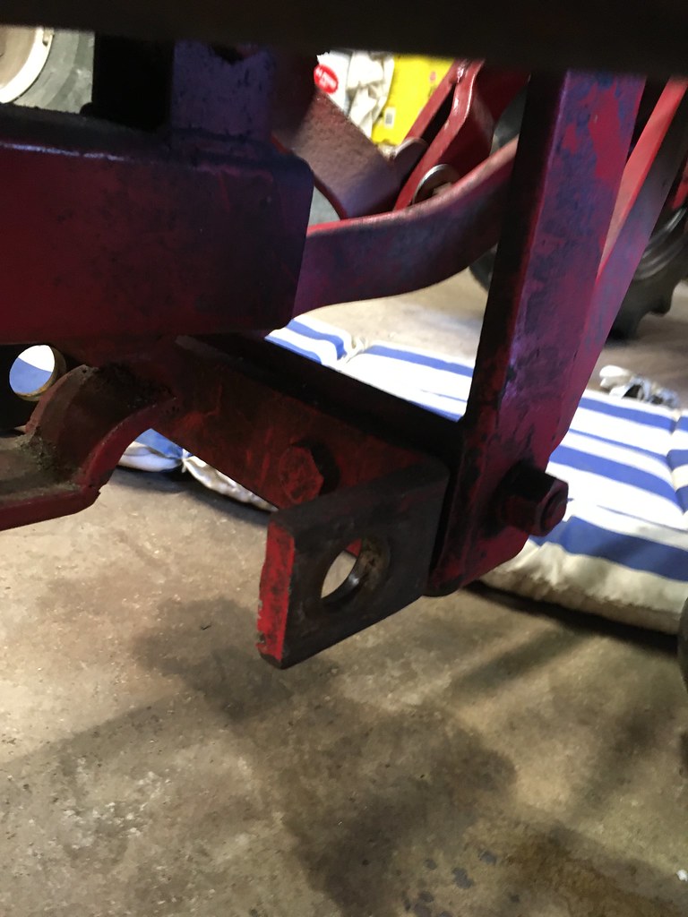
Plan “B” may be to add a piece by removI got the bracket the bar goes through and bolt up a heavy and gusseted piece of angle iron to bolt the bar mount to which would kick it forward like a Lo-Boy L54 mounting frame. That should move the frame forward so that the tires don’t rub but would that create another problem?
Also I find it hard to believe the tolerances were made this close it it would have interference issues in a factory setup.
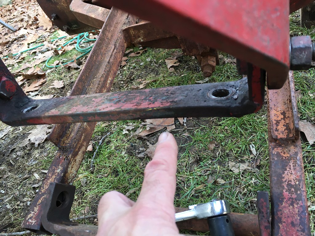
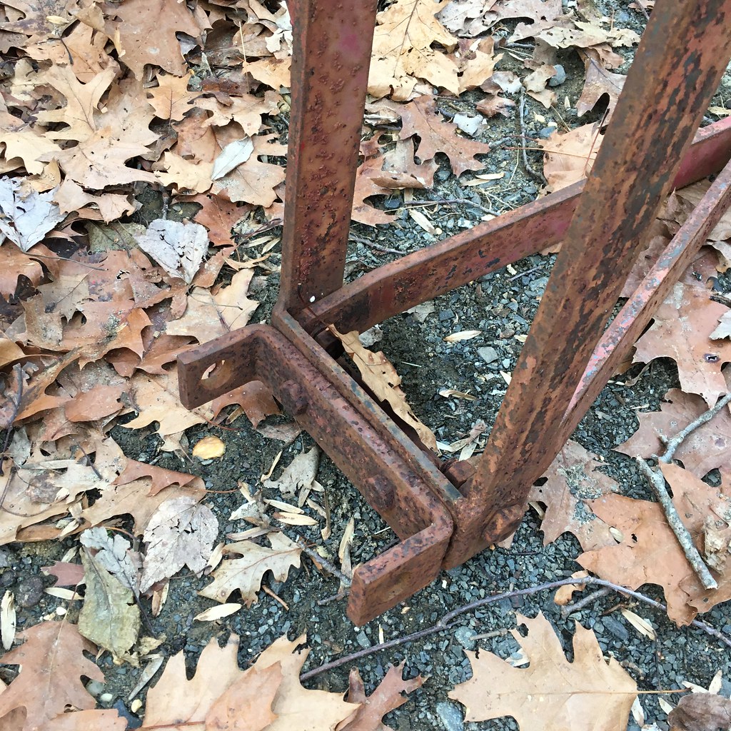
 
Having a time getting a pic uploaded and the correct link to upload here. :roll:
Don’t have access to my laptop right now but I will say the frame on this may look crusty and rough but it is very straight. I have two of these blades and compared dimensions and they match up. The frames from the bar to the bow commonly bend arching upward. The PO welded an angle iron piece to each side which may not be factory but it is a good idea and will stay.
In this pic (which I will edit in) the right tire is actually touching the frame. If I cant the blade to the left and turn the wheels to the right the left side connects as well.
OK Here'sthe pic...
I tried to circle the lower bracket where the bar goes thru connecting the plow frame to the mounting frame hanging under the bolster.
The bracket actually locates the bar a little behind center of the mounting bars coming down from the center. Its held by two bolts and tomorrow I'll remove it and turn it around to relocate the bar a little forward of center. That might be only 1" but we've seen before what a difference 1" can be.

50826995802_c27f097fc7_b.jpg
 
I think the lower bracket is normally symmetrical, so it shouldn't matter which way it is mounted. I don't have one here to look at, so maybe I am wrong. When you get it unbolted so you can get a good look, I think you may find it has been sprung. I think reversing it is a good thing to try. I also wonder if there is something off kilter back on the mounting frame (plate that bolts to the bell housing or the 2 axle braces that go from the plate forward towards the lower bracket). The effect could be to move the pivot axle hanger (where the lower bracket bolts).

If all the above doesn't cure the problem, you could look at the track width setting of the front wheels. I notice you have adjustable front rims. Setting them to a narrower position might add a little clearance. You also have an adjustable front axle. Setting it out one position would add some clearance as well. (I know it sounds strange to suggest both setting the rims narrower and the axle wider to address the same problem.)
 
Mike,

just a comment If you have the blade yawed that much to the right you probably do not want to be turning the tractor left that much while plowing. If you raise the blade is there still interference?

I was going over my blade last weekend. This is the first time I am mounting a blade it on a bigger tractor. The mount is on the tractor and I went over the blade but did not mount the blade to the mount yet. It is on a 140 but I will take some pictures this weekend. I also must have a "newer" one. I have a spring in the lifting arm.
 
inairam":2kmlqrc1 said:
Mike,

just a comment If you have the blade yawed that much to the right you probably do not want to be turning the tractor left that much while plowing. If you raise the blade is there still interference?

I was going over my blade last weekend. This is the first time I am mounting a blade it on a bigger tractor. The mount is on the tractor and I went over the blade but did not mount the blade to the mount yet. It is on a 140 but I will take some pictures this weekend. I also must have a "newer" one. I have a spring in the lifting arm.
Up or down it hits and there are times when I plow I do turn the wheel sharply as in when i taking "bites" with a heavy snow or pulling snow away from landscaping or a garage door.
I went over it better today.
Here's another shot of the wheel rubbing. Notice the pin is out because with it hitting I can't drop it in the last hole.

50829532406_94616ba7d7_b.jpg


This is the lower bracket the bar slides thru. It appears to cant rearward so I thought if I turn it around it would move the blade frame forward.

50829539001_3ca592339a_b.jpg


Nope, that part was actually straight. The mounting frame is twisted and has a weld repair on the bottom right corner.
The weld was made with it twisted so I not going to try and straighten it for fear of breaking the weld.
50829538706_3a3cd72cb7_b.jpg


"Plan B".
This is my solution. Both A60 plows I have, have identical mounting frame configuration though the other frame has the pressure spring rod assembly (needs repair). Its lower frame has a weld repair too. Could be a sign of a weak area in the plow design.
Both mount the plow to the mount with the bracket facing down like the early versions of the Cub 54 blade assemblies like the one below mounted on Paula's '52. (second gen plow I got from Coppersmith, Val Adams :hattip: )

50828782873_8cbde850e6_b.jpg


Below are the later versions of the Cub Blade mounts, One for the F-Cub, and one mounted on my Lo-Boy.
You can see how the bracket is repositioned forward and boxed together being much stronger.

50829619677_4d1e59f31f_b.jpg


50828785513_737d8a0f82_b.jpg


This is what I'm going to replicate by taking 2" angle iron cut to length, box the ends and drill 4 holes. This way its an addition and not further modifying it from its original form. This should kick the whole assembly 4" forward and I. guessing will also result in more lift for the plow.
I'll report back of course if it added the needed clearance.

Oh One more thing I did just for fun. I noticed with full down pressure on the plow the front tires lifted slightly so I raised the plow and put blocks under. It lifted the front wheels off the ground like a back hoe! I tried this with my Cubs and they didn't have the power to do this.

50829531031_54d89359d1_b.jpg
 
I think your approach to a fix is reasonable. You will want a pretty heavy (thick) angle iron to make your piece. After all, look at how heavy the existing frame is, and it bent. I notice the hole in the lower bracket is worn egg shaped. So even if that bracket isn't bent, reversing it would have helped a little.

When I am plowing, I also end up making hard left turns while the blade is angled to the right. I start at the garage door going crosswise left to right in front of the door. I make additional passes, each farther from the door. When I get below the apron, i occasionally make my pass across then swing left to clean up in front of the accumulated pile and crowd it back a little more.
 
Jim Becker":tihqkymw said:
I think the lower bracket is normally symmetrical, so it shouldn't matter which way it is mounted. I don't have one here to look at, so maybe I am wrong. When you get it unbolted so you can get a good look, I think you may find it has been sprung. I think reversing it is a good thing to try. I also wonder if there is something off kilter back on the mounting frame (plate that bolts to the bell housing or the 2 axle braces that go from the plate forward towards the lower bracket). The effect could be to move the pivot axle hanger (where the lower bracket bolts).

If all the above doesn't cure the problem, you could look at the track width setting of the front wheels. I notice you have adjustable front rims. Setting them to a narrower position might add a little clearance. You also have an adjustable front axle. Setting it out one position would add some clearance as well. (I know it sounds strange to suggest both setting the rims narrower and the axle wider to address the same problem.)
Jim your right, I completely forgot that I have the option of adjusting the front wheels and axles :oops: I’ll chalk that up to the brain fog you can get when working on your own equipment. I guarantee if it was my neighbors tractor it would have been obvious to me. :roll:
I’ll still try the bracket relocate first. Getting those axles to slide most likely won’t happen without a fight. But, it an option thanks !
 
Jim Becker":30ilynbn said:
I think your approach to a fix is reasonable. You will want a pretty heavy (thick) angle iron to make your piece. After all, look at how heavy the existing frame is, and it bent. I notice the hole in the lower bracket is worn egg shaped. So even if that bracket isn't bent, reversing it would have helped a little.

When I am plowing, I also end up making hard left turns while the blade is angled to the right. I start at the garage door going crosswise left to right in front of the door. I make additional passes, each farther from the door. When I get below the apron, i occasionally make my pass across then swing left to clean up in front of the accumulated pile and crowd it back a little more.
Exactly!
I hate the idea of the frame capturing the wheel when I’m close to a door. This thing is a bear compared to a Cub and could potentially do some damage.
Our local iron works closed its doors from its original location 5 miles away and built a new huge warehouse right on my road a stones throw away :) . They have anything I could want and their prices are pretty reasonable.
I’ve been in there a couple times a month since becoming my neighbors.
 
Mike

You got me all worked up about this. I had not thought of this as a problem. I just found a pic of the front end and my front axle is moved out but I have the larger wheels/ tires. Hopefully, I will not have this problem.

Good luck. I also think you have a good plan. I would try to minimize the pushing forward of the blade to give your tires clearance. It just does not take much to lighten the rear wheels. The more leverage the blade has the less weight on the rear.
 

Attachments

  • redlr.png
    redlr.png
    347.4 KB · Views: 707
Could you replace this plate or weld a heavy tang on it with a hole so that the supports going forward to the belly cradle get shoved forward? That would buy you some extra clearance. I had this same issue with my '48 Cub owing to my plow pivot points being sloppy. So I used a longer plate between the implement mount and the supports. Worked great!
 

Attachments

  • superA.PNG
    superA.PNG
    362.4 KB · Views: 693
Urbish":130bbt8a said:
Could you replace this plate or weld a heavy tang on it with a hole so that the supports going forward to the belly cradle get shoved forward? That would buy you some extra clearance. I had this same issue with my '48 Cub owing to my plow pivot points being sloppy. So I used a longer plate between the implement mount and the supports. Worked great!
That would slant the mounting frame forward and change how the force from the plow is directed back into the torque tube.
I'll see what my part I'll make up does then try adjusting the wheels next and if I have to I'll widen the axles.
I really don't want to widen it because its tight enough squeezing it into the shed it shares with 2 other tractors and an Exmark zero turn.

* here's a tip: You can see in the photo of the lift assembly I have drilled and pinned the connecting bolt. In fact once this has been properly restored it will have longer bolts that are thru bolted on all of the blade assembly that are on pivot points. It saved me from walking up and down a snowy driveway or fishing for replacement bolts in the barn when they work loose. Raising and lowering the plow will loosen and bolts that secure two parts that have even the slightest bit of movement. There's a lot to watch when plowing and constantly checking bolts can't be one of them.
 
OK, I’ve been busy the last two days with getting a cat to the vet, running errands but I did manage to get to the iron works and get some fabrication done. As long as I was at it I picked up a 8” x 60” x 3/16” steel plate. I located the plate on the blade and marked the locations for the holes, drilled them, ground the burrs, rounded the corners and dulled all the edges.
Ever walk into a grader blade? If your lucky it’ll only cut your pants. ;)
So with that done I bolted it up and my snow blade is 90% done. All that’s left with that is to give it its curve and paint. I plan on using my shop press and a Cub blade as a form to give it the curve the factory snow extension plate had.
Ok on the bracket. I bought 2” x 1/4” angle iron for that. It will work but having made most of the part I’d go with 2-1/2” x 5/16” angle.
I bolted the bracket I made up and it kicked the plow frame 3-1/2” forward. The interface issue is no more ! There’s probably 2-1/2” to 3” between the frame and tire now. Kicking it forward did lift the plow as well. All the way down as it was setup before it has an inch of air under the blade.
The lift arms are on the bottom hole, put to the top and it’ll have ground contact again.
I’m going to fiddle around with it some more to move it back a hair. I’ll add gussets afterward to beef it up.
 
Mike

Please post some pictures of the mod.

I mounted the blade today. Full right yaw of the blade I have a carriage bolt that may catch. I have two holes showing on the axel and have the larger front tires.
 

Attachments

  • plowangle.png
    plowangle.png
    706.2 KB · Views: 614
inairam":93b1d506 said:
Mike

Please post some pictures of the mod.

I mounted the blade today. Full right yaw of the blade I have a carriage bolt that may catch. I have two holes showing on the axel and have the larger front tires.
How big are those tires? I have the 15 x 5.00 fronts on mine.
 
Ok here are some pics of the results.
Relocating the bottom bracket kicked the frame 3-1/2' forward and you can see it provided plenty of room.
You can see the before and after....
Before...
50826995802_c27f097fc7_b.jpg


After...
50839491316_e1d4161a9c_b.jpg


Edit: You might notice I replaced the bolts for pins where the blade connects to the frame. Much, much better.
50839573857_b0a655a056_b.jpg


A closer look at the bracket I made. Its not gusseted yet and will be stronger when I do. this was 2 x 1/4" angle iron, the same width as the frame but not as thick. I would use 2-1/2" x 5/16" or 3/8" angle next time. Once this is gusseted I don't think it'll bend or break but if it does that's what I'll do.

50838767203_833276572f_b.jpg


Here's some shots of the grader blade.
Fazzio's Iron Works sells the plate steel in 6,8,10, and 12" widths and 5 or 10' lengths.
I asked for 5' (60") 8 x 3/16" plate steel and expected to have to trim an inch off but it was an exact match to the blade ! :)
I drilled the holes, removed the burrs, then rounded the corners and dulled the edges because I'm bound to walk into it. :roll:

50838767208_3076b85e9c_b.jpg


50838767223_e07ab28a04_b.jpg


If this were a Cub blade it would be done because they are flat but the A60 snow extension follows the curve of the blade.
I plan to take an extra Cub blade I have and lay it across the shop press to use as a mold to form the curve.
We'll see how that goes. It may be simple but its cool to replicate a factory part from scratch.
I brought the pins up one hole on the blade to the center and it has no problem contacting the ground now in fact when it wouldn't touch before it lifts the front wheels now.
 
Lt.Mike":53o2a18u said:
inairam":53o2a18u said:
Mike

Please post some pictures of the mod.

I mounted the blade today. Full right yaw of the blade I have a carriage bolt that may catch. I have two holes showing on the axel and have the larger front tires.
How big are those tires? I have the 15 x 5.00 fronts on mine.

This is a 140 with larger tires and rims. It has 11.2 x 24 on the back and I think 16" up front. I have a 130 and a 140 with the 9.5x 24 and 15". The tires on this one are noticeably bigger.

I may do this. I think it will be easier to mount plus move it forward.
 
Looks like a winning solution there, Mike. I agree that you will probably want to weld in some gussets on that piece of angle, but this oughta be a solid solution that will last for a very long time. Nice work, and thanks for sharing photos!
 
Urbish, thank you! :hattip:
As for sharing photos, their not the "how too's" Dale puts up but I'm trying.
What can I say? She's a hard act to follow ! :lol:

Inairam, this had 9.5's on the rear when I brought it home but I swapped them for 11.2's that I had on my A. The A has 4.00 fronts which look better with the 9.5's anyway.
The 2 x 1/4" angle I used will stay as I have sweat equity into it :) but when you make yours go with the 2-1/2" angle as it is thicker/stronger.
As for being easier to mount :roll: I guess you already noticed how heavy this thing is. :shock:
I used a ratchet strap hooked to the top of the lifting lever then the frame to lift the plow frame up to where i could start the bolts. I don't mustle things around like I used to. :(
 
Lt.Mike":eig5ksz1 said:
I guess you already noticed how heavy this thing is. :shock: :(

Well the 54 blade I manhandle to move it. This I had to think.

BTW in the manuals, which I think shows an A, the blade looks to have plenty of clearance. In real life, the distance is much shorter. I wonder what the issue is.
 
Back
Top