Charging system 1952 cub

Workinprogress

Well-known member
Working on electrical charging system but getting a little confused on what have and where to go.

System running 6 volt battery with positive ground and a magneto.

Currently has delco 1100501 generator with 3 brushes.

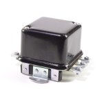
Has Voltage regulator which is mounted on top of the generator.

It did have a 4 way light/load switch which I replaced with a standard 3 way switch because all the external connections contacts were badly corroded.

I also just replaced the entire wiring harness with a brillman harness set up for regulator.

Currently I get no reading on the amp gauge (to the right) when the tractor is running. I wanted to try the headlights to see if gauge does anything but both bulbs burnt out. Figure a quick stop at the local autoparts store would find me a couple bulbs. Three stores, all failed. Was able to rig up 12 volt bulb with test leads and got amp gauge to go a little to the left when I turned the lights on. So I think the amp gauge functions.

So before I start down the trouble shooting path does the system seem correct? Specifically that model generator with a voltage regulator using a 3 way light switch.
 
you need to back up, you have a cut out relay, not a regulator and the 4 way switch controls it, 3 way switch was not, here is a flow chart for the cut out system
 

Attachments

  • 07-Cutouttroubleshootingchartrev1_0.gif
    07-Cutouttroubleshootingchartrev1_0.gif
    59 KB · Views: 502
Hi,
Tim, he said it's a 1952 Cub, they have the 1100501 generator, and the voltage regulator on the plate beside the gen, not on top of it.
They also have the 3 position light switch, for only the lights.

IH started using that at serial number 115403.
Check your serial number, and be sure it is a 1952 Cub.

I don't know why the voltage regulator would be on top of the gen if it is a 1952 Cub.
Someone changed it I guess.
Below is a page from the 1955 Cub operator's manual showing the Cub with the hood off, you can see where the voltage regulator is.
The voltage regulator has 4 posts for wires to connect to it.
The cutout or Relay IH called it has 3 posts for wires. It was used up to serial number 115403. It is mounted on top of the generator.
There are voltage regulators made that mount on top of the gen, IH didn't use them on Cubs, they aren't in the Cub parts manual.

http://farmallcub.com/rudi_cub/www.clea ... age-39.jpg
 
try and post a pic of the generator regulator so we know what you have for sure and your serial # to verify year
 
This is exactly the problem I am trying to figure out. Yes the tractor is a 1952. The serial number is 146,920.

What I am finding is over those 70 years parts have been exchanged. For example the hood is set up for long eared dash but the current dash is a short eared. This may be where the 4 way switch comes into play.

Regardless of what it once was I am trying to figure my path forward to make this a dependable functioning tractor based on what is on it now. Also I am trying to deal with the parts I already replaced without fully understanding the details (ie the light switch).

The unit does not have a cutoff relay unless they made them with 3 electric connection tabs on the side and a forth under it.

F922E877-235E-4B4A-9A4C-D0CDA767B0A9.jpeg

A845BA42-59C7-4325-96B4-4588C3B90D3B.jpeg

9930BF08-2907-4462-B15A-A44C7BC8260A.jpeg
 
Workinprogress":35jixv70 said:
I am trying to figure my path forward to make this a dependable functioning tractor based on what is on it now. Also I am trying to deal with the parts I already replaced without fully understanding the details (ie the light switch).
Consider a 12 volt single wire alternator.
The unit does not have a cutoff relay unless they made them with 3 electric connection tabs on the side and a forth under it.
Voltage regulators have a cutout relay. The purpose of a cutout relay is to disconnect the generator from the battery when the tractor is not running.
 
I have a battery tester that looks like this and It is my go-to device. it reads voltage and tests the battery and the charging system for both 6 and 12 volt systems

Did you replace the regulator? If so where did you get it? I have had 6 volt imported regulators DOA out of the box. NAPA has the VR851 but it is not designed with the rounded mount to mount on the generator. I think Brillam sells a regulator like that.

You should not need a hose clamp to mount the VR. There should be taped holes in the generator case. If there are no taped holes maybe you need to do the plate mount for the VR
 

Attachments

  • battertester.jpg
    battertester.jpg
    120.4 KB · Views: 467
I don’t have a battery tester like that but do have a couple digital multimeters. So far I haven’t done any testing as I am trying to understand what I have before I start testing.

The voltage regulator was on the tractor when I purchased it.
 
Workinprogress":2xh2bh8o said:
This is exactly the problem I am trying to figure out. Yes the tractor is a 1952. The serial number is 146,920.

What I am finding is over those 70 years parts have been exchanged. For example the hood is set up for long eared dash but the current dash is a short eared. This may be where the 4 way switch comes into play.

Regardless of what it once was I am trying to figure my path forward to make this a dependable functioning tractor based on what is on it now. Also I am trying to deal with the parts I already replaced without fully understanding the details (ie the light switch).
It's also possible that someone in the past changed the bolster and kept the SN so that you appear to have a 52 but it might be older or newer. A cross check of the major casting codes might reveal that it contains parts from different years of manufacture. JMHO
 
Yes I have already checked the casting codes and part numbers for the clutch housing/tube, final drives, right extension tube for rear axle. Everything seems correct for that year and serial number range. At least was correct. I have had to replace some of the cast parts.

Maybe I need to focus my question.
1. Is the Delco 1100501 generator designed for a voltage regulator instead of a cut out relay?
2. Is the correct location of the voltage regulator below the generator on a mounting plate? Tm sells that plate but it seems pretty simple
http://www.tmtractor.com/new/el/952fp.htm
 
that is a regulator someone clamped to the generator, so follow the wiring diagram for a regulator system to verify its wired correctly to start with, then just follow this flow chart to help find the issue with it not charging, regulator should be mounted for good grounding, hose clamp does not cut it
 

Attachments

  • 08-Regulatortroubleshootingchartrev.gif
    08-Regulatortroubleshootingchartrev.gif
    56.3 KB · Views: 433
Since there is another thread going on about a similar problem, it is a little hard to keep track of what is going on in this specific case. But this seems to be what we have so far:

1) The tractor is a 1952, but that is irrelevant because of #2.
2) The entire electrical system, including the distributor has been stripped off and replaced with components from an earlier tractor, including a magneto.
3) The tank/hood has been replaced with an earlier ('47-'49) version, maybe from the same tractor as the electrical components.
4) The cutout, which would have matched the existing generator has been replaced with a later regulator designed to replace a cutout.
5) The replacement regulator is held on by a hose clamp rather than two screws as designed. This almost guarantees a poor ground connection for the regulator.
6) The 4-position light switch, part of the '47-'49 components, has been replaced with a 3-position switch. This is okay because of #4.

This is what you should do next:
1) Cleanup and verify contact of all electrical connections, paying particular attention to the grounds. The most obvious concern is the grounding of the regulator onto the generator. There should be two existing tapped holes in the generator for attaching the regulator. Don't use screws any longer than needed. They should not be longer than the thickness of the generator shell.
2) Check to see if it now charges. If not, go through the troubleshooting chart that tst posted.
 
Workinprogress":1p4f0x7j said:
Maybe I need to focus my question.
1. Is the Delco 1100501 generator designed for a voltage regulator instead of a cut out relay?
2. Is the correct location of the voltage regulator below the generator on a mounting plate? Tm sells that plate but it seems pretty simple
Hi,
1. Yes, the Delco model number 1100501 is the generator IH used with the voltage regulator, from when they began using the regulator, at serial number 115403, which was during 1950, until during 1956, when they changed to the next model number of gen that they used.
It is what my Cub has.

2. Yes, the regulator goes on a mounting plate beside or below the gen.
The plate TM sells is the right one. The plate goes on below the gen mounting bracket, so the bracket is on top of the plate, with the curve down. That is so the hood will not hit on the top of the regulator.
Be sure the 2 mounting bolts that hold it on the engine are long enough.

I posted a page from the 1955 Cub operator's manual in my post on page 1 of this post, showing with the hood off, it shows the regulator mounting.
The 1952 Cub operator's manual shows it also.

The part in your pics is a voltage regulator. It looks like the original style that IH used on Cubs in those years, but I can't see the mounting of it too well in your pics.
If it has the curved mounting to fit on top of a gen made on it, it has been replaced, that style wasn't original.

The regulator should have a flat base for 2 bolts, like the mounting plate has.
The original regulators had the Gen post under it, that is so the wire would be out of the rain, or out of sight when installed on the plate.
The regulator originally faces with the 3 posts in toward the engine, so the wires are not seen.
The bottom wire goes under the reg, so it is not seen.
Be careful with the wire routing, be sure none of them rub on the throttle rod going to the governor.
The rod moves, and eventually it could wear into the wires.

The F and A wires from the gen to the regulator go around the left side of the gen, and follow its shape, curving down and around under the gen, to the regulator. Make them the right length if you are making your own wires.
Make them a little longer, so the gen can move out from the engine if the belt wears, and you need to adjust it out.
You should have a gen belt that makes the gen in on the adjustment slot, so it can be moved out as the belt wears.

Your Cub could have come new with the magneto, they were available then.
Or someone could have changed it to a magneto.

The 3 position light switch is supposed to be on a 1952 Cub, they were used from serial number 115403 until 210000.

Like Jim said, the hood has evidently been replaced with one for a Cub older than yours.
A 1952 Cub originally has the short ear dash.

Below is a pic from Brillman, I think, of a Cub voltage regulator showing the mounting.
It has the Gen post on the side, that is the newer way they are made.
The post under the reg is nice, it keeps rain off it. :)
 

Attachments

  • Cub voltage regulator 6 volts B.jpg
    Cub voltage regulator 6 volts B.jpg
    35.4 KB · Views: 256
Eugene":cb55jylt said:
Consider a 12 volt single wire alternator.
Can be installed for about the same price as a quality voltage regulator. Tractor is much simpler, dirt simple, to wire. Less headache than trying to figure out the current trctor's wiring.
 
Success!!!!!!!!

I cleaned up the armature on the generator. Did the spin test with the generator using jumper cables and the 6 volt battery. Generator spun when given power. I walked around the tractor and noticed a wire in the regulator was broken! See photo below.

37D386A3-C621-4C6E-9AFF-7F9CB76069FE.jpeg

I rigged up a temporary wire to test. Everything works! Amp meter was reading over 10 at 3/4 throttle!
 
Back
Top