Battery drain & possible diode location for a 12v alternator conversion?

Dale Finch

501 Club
I'm helping a friend with a 1952 Cub, 12v battery ignition, with Delco Remy Alternator. He says the battery drains in a short period of time (when not running), and though he has recently replaced the battery it continues to do so. I have read through a bunch of posts, and will be attempting to trace down the problem by disconnecting electrical components one at a time, with a meter connected in series with the battery and the disconnected battery cable.

Meanwhile, I have read several posts that mention a diode being placed in the circuitry to prevent draining the battery while not running. My question is: Where is the diode wired in, which direction, and is the 1N4001 the correct diode? I did find this wiring diagram (#5 titled "12v alternator conversion schematic for Farmall Super M", updated Jan '08)

file.php

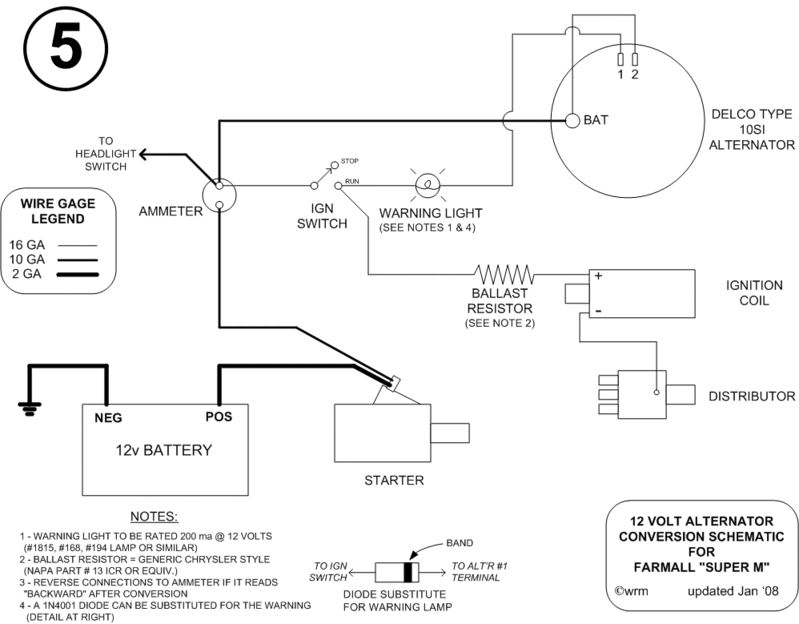
To clarify, and because of proximity, can I add the diode between the #1 spade on the alternator and the + side of the coil? Note: the coil is a 12v Internal Resistor, so no external resistor. Do I also need to add the jumper wire between the #2 spade on the alternator and the BAT terminal on the alternator?

This is the alternator currently installed:
20211008_110023 (Small).jpg
20211008_110155 (Small).jpg
 
Dale:

The wiring diagram and instructions are correct for the Cub.

I didn't see any wires connected to #1 and #2 terminals on the alternator. Check for the amp loss with wire #1 disconnected, common problem site.

Opinion. Exchange the alternator for a one wire Delco clone at the auto parts store. Use to be $35- plus the old alternator.

Edit: Terminal #1 excites the alternator. Terminal #2 is for the regulator.

There are a number of methods to excite the alternator and then disconnect the #1 terminal. I use a toggle switch. Other use an oil pressure switch.
 
it appears to have a black rubber type plug /cover on the two spade terminals ??? if so it is probably a one wire conversion alternator, should only need battery power at the alternator to charge, wiring looks pretty hacked from what can be seen in the pic
 
In the diagram, the diode would be installed in place of the warning light, with the arrow pointing toward the alternator. You want current to flow TO the alternator, not back toward the ignition coil.

I agree with the other assessments. The terminals on this alternator are blocked off so it is a one-wire alternator. No diode, warning light, or wires to the #1 and #2 terminals are required at all in this setup.
 
Eugene":3u4d9g33 said:
Dale:
The wiring diagram and instructions are correct for the Cub.

I didn't see any wires connected to #1 and #2 terminals on the alternator. Check for the amp loss with wire #1 disconnected, common problem site.
There are NO wires currently connected to the #1 &2 terminal lugs. Those are the ones I am asking whether I need to add in order to stop the battery drain.

Matt Kirsch":3u4d9g33 said:
I agree with the other assessments. The terminals on this alternator are blocked off so it is a one-wire alternator. No diode, warning light, or wires to the #1 and #2 terminals are required at all in this setup.
Then can anyone offer a suggestion as to the source of (& cure for) the battery drain?

I removed the rubber cap to show the two terminals (#1 & 2).
20211011_172403 (Small).jpg
I had thought from various posts that adding the diode between #1 and the + side of the coil (equivalent to the run side of the ignition switch...just closer physically) was the solution several folks suggested.

Here is the current wiring diagram, but with the proposed diode and jumper (click on image to enlarge):
20211011_180404_LI (Medium).jpg
I do appreciate the input. My friend does, too! Thanks for your help.

And I really did not think the wiring looked hacked...it is in better condition than most I have seen.
20211011_172554 (Small).jpg
20211011_172615 (Small).jpg
 
Dale:

Connect multi-meter as you previoauly described. See if you still have amp or volt draw. Yes. Disconnect the battery terminal on alternator.

Voltage/amp draw disappears - internal voltage regulator at fault. Doesn't disappear - gonna have to look for another problem source.
 
Dale, if your testing reveals that the drain is caused by the alternator, it has a shorted internal diode, just replace it. The diode in the excite lead (not applicable here) is only to prevent back feed from the alternator to ignition, which prevents normal engine shut down. Do your testing before jumping to conclusions.
 
Dale Finch":m05nnvqv said:
Matt Kirsch":m05nnvqv said:
I agree with the other assessments. The terminals on this alternator are blocked off so it is a one-wire alternator. No diode, warning light, or wires to the #1 and #2 terminals are required at all in this setup.
Then can anyone offer a suggestion as to the source of (& cure for) the battery drain?

Having the #1 and #2 terminals connected improperly, without the diode or idiot light, will cause *A* drain.

If they are not hooked up, they can not possibly be the source of your drain and hooking them up will not fix your issue.

Some one-wire alternators drain the battery. That's how they are. You take it back to the auto parts store and complain, and that's what they tell you.

Right now I'm one for two. The one-wire on Dad's Super M doesn't, but the one-wire on my Super M does drain the battery.
 
Any drain through the alternator should be only very slight, in the miliamp range. You should be able to park the tractor for months, without appreciable discharge of the battery. If the parts store is telling you that is normal, find another parts store that will stand behind what they sell.
 
OK...thanks Gary & Matt.
Today I'm heading to the farm to do some road maintenance, and will probably stay overnight. So testing will be in a couple days.

I will post results.
 
Gary Dotson":1aqgtnir said:
Any drain through the alternator should be only very slight, in the miliamp range. You should be able to park the tractor for months, without appreciable discharge of the battery. If the parts store is telling you that is normal, find another parts store that will stand behind what they sell.
Decided to test before I leave for the farm...

With neg ground disconnected, and all wires in place, tested between the neg batt terminal and the cable. (No switches on, tractor not running)
NOTE:. Small white & black wires on battery cables are pigtails for a trickle charger hookup)

20211012_104214_copy_1008x567.jpg
20211012_104253_copy_1008x567.jpg
20211012_104312_copy_567x1008.jpg
I then disconnected the alt wire, and no current flow:

20211012_104133_copy_1008x567.jpg
20211012_104116_copy_567x1008.jpg
The draw seems pretty high. Is this strictly an alternator "internal" issue? Would it be easier to just go ahead and swap it out for a different alternator? I think the owner would be happy to pay if it meant no more dead battery!!
 
I'd probably remove the alternator and take it to an auto parts store to have it checked.

Other options include purchase a new alternator and temporarily wire it up (before mounting it) and re-test the Amp Draw like you did above. If improved, install the new alternator. If no improvement, return the alternator and investigate further.
 
Looks like about 1.5 amp draw, as I said earlier it has a shorted internal diode. The 10si is extremely easy to repair but considering the low cost of a re-man, that will be your best route.
 
I think I'll recommend replacing the alternator... it's not a huge investment and if it resolved the issue, he'll be quite happy!

NOW, that dreaded question...what is currently the best one to get? I've seen several suggestions over the years, but ask to get a consensus on what is out there now.

Thanks!
 
Dale:

I use the Delco 10SI single wire clone from the auto parts store. I have had no problem with them.

Exchange the current alternator. It's not cost effective to repair the current alternator, You will only save a couple of dollars. The new alternator will/should have a 1 year warranty.

Edit. At the auto parts store, during the core exchange, check to see that the pulley on the new alternator is the same as the old one.
 
Gary Dotson":39wc6ign said:
Looks like about 1.5 amp draw, as I said earlier it has a shorted internal diode. . . .
I read that multimeter as set to measure 5 volts with a reading of less than 1 1/2 volts. Without knowing the internal resistance of the meter, I can't use that reading to infer current. I question whether that is high enough to even be a problem.

Maybe something else (or nothing) is going on here. I wouldn't condemn the alternator based on what I see. If nothing else, unhook the wires from the alternator and repeat the same measurement.
 
If you enlarge the photo of the multimeter, the INDEX is at the 12 o'clock position, making the scale 250mA.
With the wire to the alternator removed, 0amps.
With the wire attached, I read 60+ mA.

Do you concur?

I know meters are designed differently...on this one, the selected scale is always whatever is at that 12 o'clock position.
 
Dale Finch":2yym01vw said:
Do you concur?
Yes, concur. Amp draw disappeared when the alternator was disconnected. No other appliance turned on - - alternator problem.

Amazon. The diode bridge and regulator is $35-.

My preference. I would have used a digital mult-meter for the current check. Direct reading on the display.

Also I have several of the Harbor Freight digital multi-meters. They are inexpensive, quite accurate, not a big loss when they get smashed up.

Edit: My single wire 10SI's have an amp draw of 5 mA. It would take a while for the 60 mA to draw down a fully charged battery in good condition.

Clean up the battery cable terminals/ends and cable connections.

The battery doesn't appear to be new. Have battery tested or do a voltage drop test. If good, wash top with baking soda and water.
 
Dale Finch":hpq70ug7 said:
If you enlarge the photo of the multimeter, the INDEX is at the 12 o'clock position, making the scale 250mA.
With the wire to the alternator removed, 0amps.
With the wire attached, I read 60+ mA.

Do you concur?

I know meters are designed differently...on this one, the selected scale is always whatever is at that 12 o'clock position.
Agreed. I didn't see the dot at 12 o'clock and assumed the labeling was fixed and the bar of the knob was a pointer.

Connecting as you did and using it as a volt meter is a very sensitive way to check for a current leak.
 
Back
Top