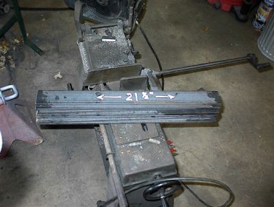
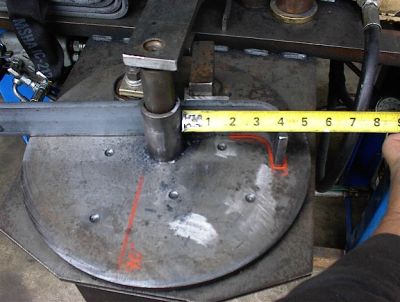
The next step is to place each piece onto the turn table. These tie-downs use an 1-5/8" diameter curve to form the shape. I built the "ELMER-2" with a center pivot shaft of 1-3/16", which is what the steps use for the top hook. This way all that needs to be done to bend the tie-downs is drop this piece of pipe over the center shaft to create the 1-5/8" bend. I also have another special made bracket that allows a short bite onto the material.
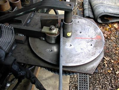
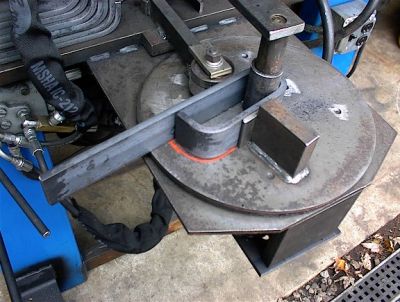
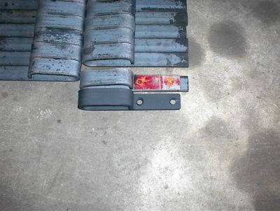
The next step is to bend each piece around till they reach the "orange" paint line drawn on the turn-table. This line stops each piece at the 90 degree bend needed.
Here's all the pieces with the bend on the ends.
Now I slide each piece through until they line up with the orange painted curve on the turn-table. If you're careful to place each piece exactly at the same spot, all the bends match near perfect.
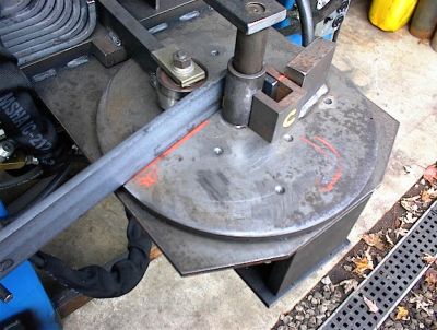
Each piece is bent completely around the center post till it touches itself.
This next step is for you drspiff :shock:
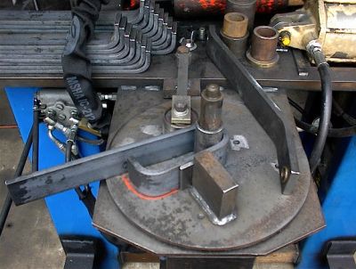
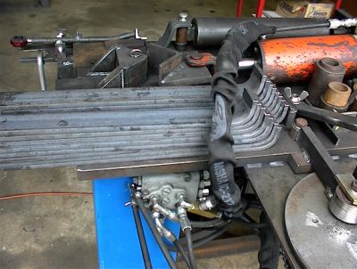
Here's 8 sets ready for welding.
Each tie-down is squeezed tight together and welded. Then I have a template that clamps on each piece to pilot drill the spacing for the implement bolts. A heavy chamfer is added and the extra material cut off the end to get things exact.
These used to be the hardest product to bend, and after you were finished, you called it a day. Now with the "Elmer 2", these are fun
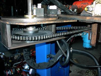
Here's an under shot of the "Elmer 2" showing the blue hydraulic motor driving the big sprocket.
Thanks,
Rick