Bill E Bob
501 Club
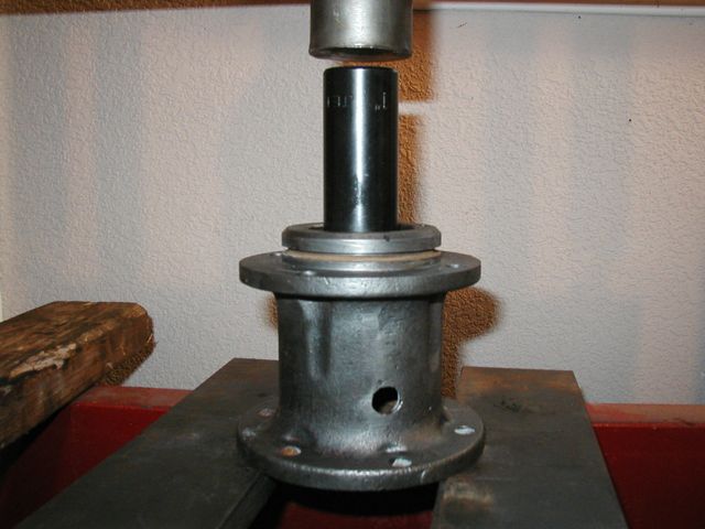
Disassembly is (obviously) the reverse of the assembly procedure. The only questionable part for me was removal of the expansion plug. I accomplished this by using the belt pulley shaft as a press shaft and pressed both the expansion plug and belt pulley shaft out of the housing using a shop press. Both items survived the operation. This, of course, was done AFTER removal of the drive pinion gear and shaft.
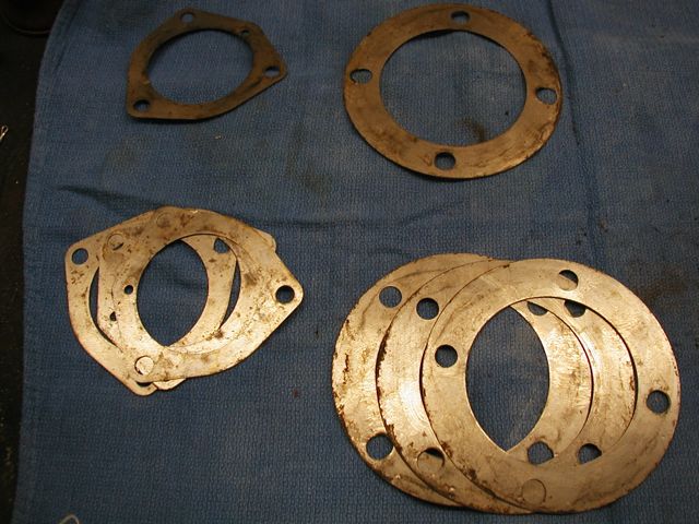
This first picture shows an exploded view of the drive unit including all seals, gaskets, o-ring, shafts, gears, shims, retainers, housing, expansion plug, spacers, keys and fasteners.
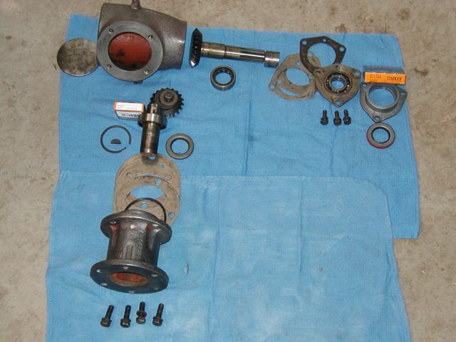
I inspected all parts and found the only ones needing replacement were the two oil seals. I obtained mine from Allied Bearing. (A local supply house in Tulsa).
The p/ns for the seals are: National oil seal 471765 and 441319. (as of 11/30/09).
I first reassembled the unit without the seals or o-ring to check the backlash (play) in the drive unit gears.
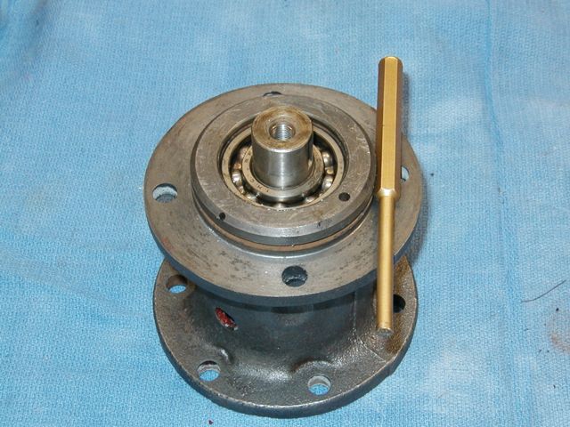
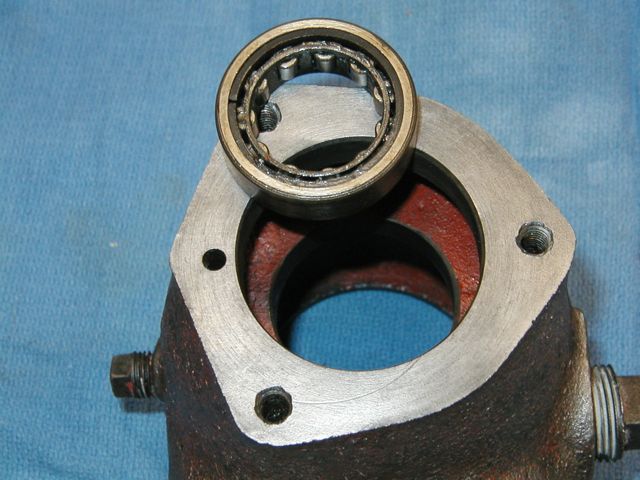
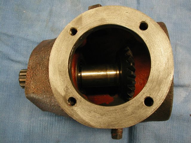
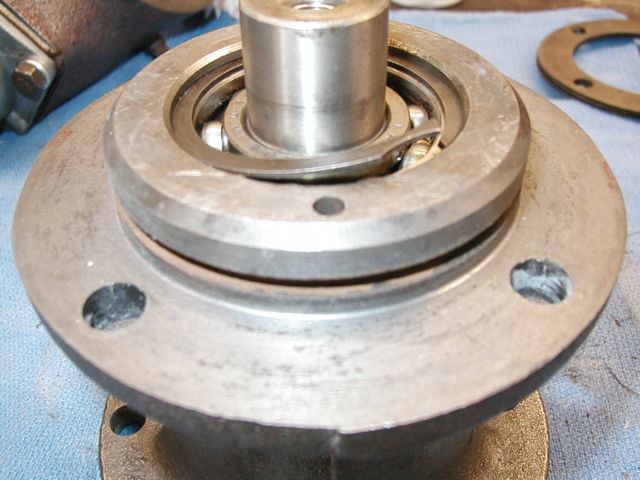
I used a brass pin punch to seat the bearing. Note the o-ring groove in the housing.
Backlash, or "play" in the gears is adjusted by addition or removal of shims. My unit required no change.
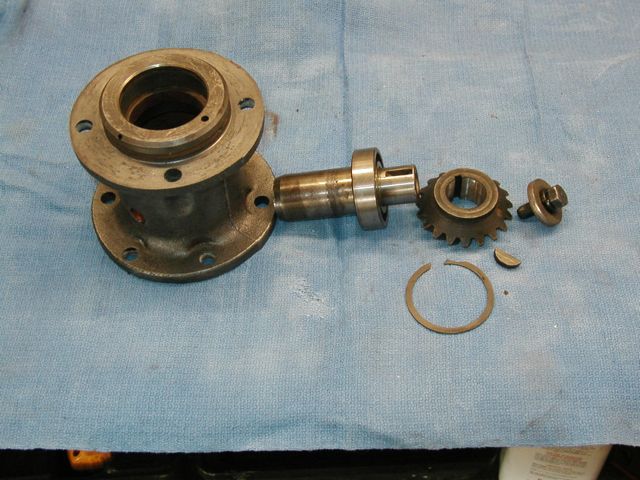
I then disassembled the the unit in preparation for final assembly.
I first pressed the inner belt pulley shaft bearing into the housing.
I then pressed in the outer bearing and retainer with shims using a 1" deep well socket as a press collar. Note proper orientation of shims when installing.
The next step was to press the oil seal into the retainer using my HF bearing race and seal installer in the press. Since the replacement seal is much thinner than the original I was able to adjust the depth of the seal in the housing so it would run on a smooth area of the spacer on the shaft.
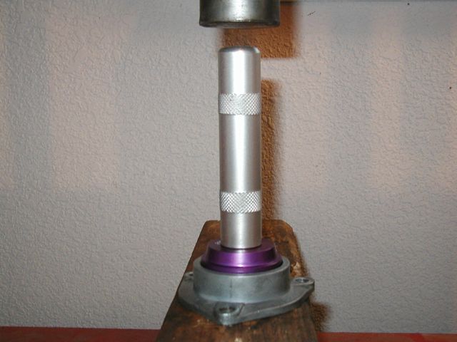
Next step was to install the belt pulley shaft.
I then started reassembly of the drive pinion and shaft into its housing.
I first pressed in the oil seal and coated it with assembly lube. Since this seal was also thinner than the original, I was able to adjust the depth so the seal could ride on the smoothest part of the shaft.
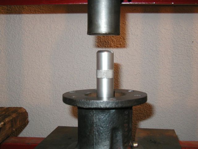
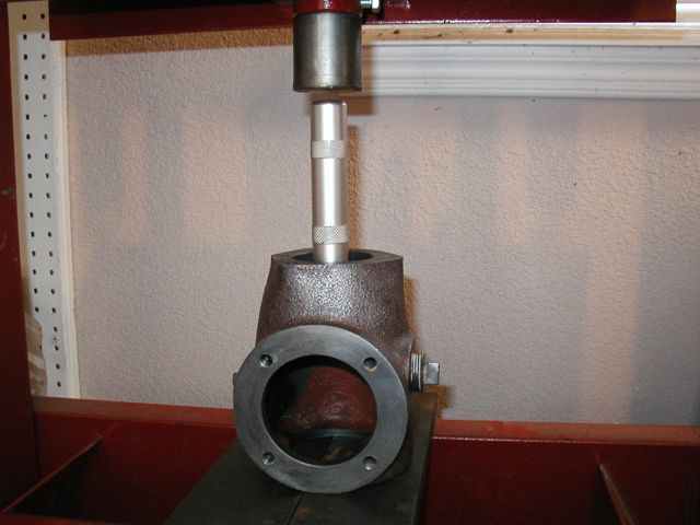
The next step was to press in the drive pinion shaft and bearing (after applying assembly lube to the shaft) using a 1" deep sell socket as a press collar.
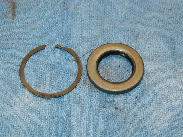
I then installed the bearing retainer clip.
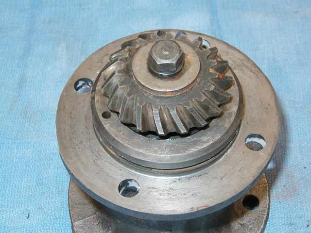
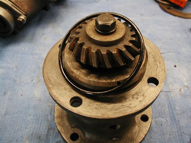
Next was installation of the woodruff key, the drive pinion and the drive pinion capscrew.
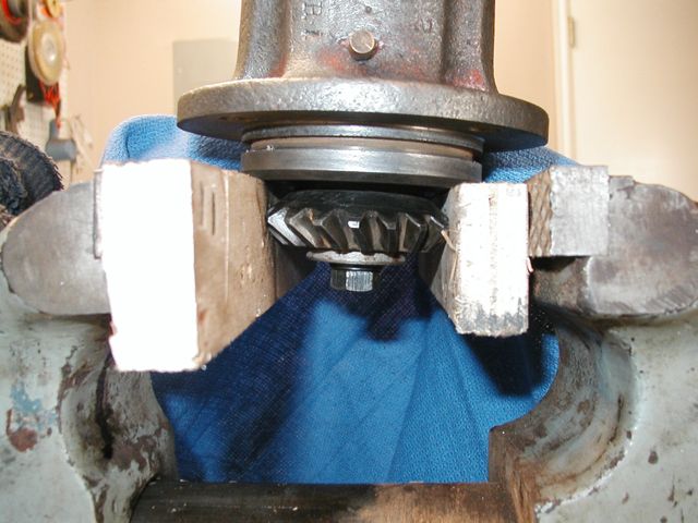
The GSS-1411 Manual calls for 35 ft/lbs of torque on the capscrew, so I clamped the pinion in a vise between two pieces of scrap wood and set the torque.
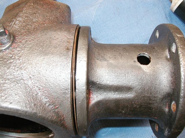
I lubed and installed the o-ring in its groove.
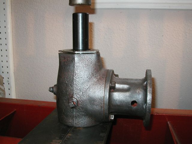
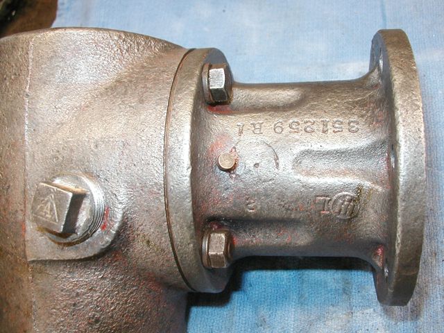
And then installed the drive pinion housing (with shims) onto the belt pulley housing. Please note orientation of the vent (center of picture). It should be up when the drive is installed onto the tractor. I torqued the capscrews to 20ft/lbs.
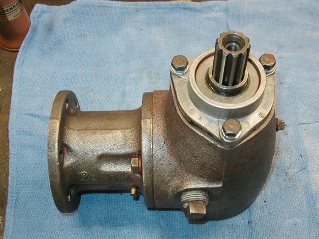
I then installed the belt pulley shaft spacer, seal retainer (with new seal), and gasket (note orientation of gasket) and torqued the capscrews to 20ft/lbs.
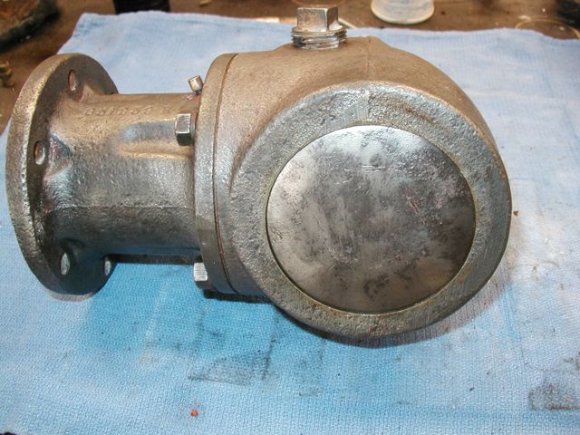
The last step was installation of the expansion plug. I reused the original as it was in good shape and rather robust ( approx. 1/8" thick) I used Permatex type 1 hard setting gasket sealer around the edge of the expansion plug and the groove in the housing. I used a large hammer to seat the plug.
I used the GSS-1411 service manual as my source document. I was able to reuse all parts except the oil seals and o-ring. Reassembly steps may vary from the GSS-1411.
Tools used:
Shop press
Bearing race and seal installer
Torque wrench
Screwdriver
Hammer.
Materials:
National Oil Seal 471765
National Oil Seal 441319
O-Ring 232
This first picture shows an exploded view of the drive unit including all seals, gaskets, o-ring, shafts, gears, shims, retainers, housing, expansion plug, spacers, keys and fasteners.
I inspected all parts and found the only ones needing replacement were the two oil seals. I obtained mine from Allied Bearing. (A local supply house in Tulsa).
The p/ns for the seals are: National oil seal 471765 and 441319. (as of 11/30/09).
I first reassembled the unit without the seals or o-ring to check the backlash (play) in the drive unit gears.
I used a brass pin punch to seat the bearing. Note the o-ring groove in the housing.
Backlash, or "play" in the gears is adjusted by addition or removal of shims. My unit required no change.
I then disassembled the the unit in preparation for final assembly.
I first pressed the inner belt pulley shaft bearing into the housing.
I then pressed in the outer bearing and retainer with shims using a 1" deep well socket as a press collar. Note proper orientation of shims when installing.
The next step was to press the oil seal into the retainer using my HF bearing race and seal installer in the press. Since the replacement seal is much thinner than the original I was able to adjust the depth of the seal in the housing so it would run on a smooth area of the spacer on the shaft.
Next step was to install the belt pulley shaft.
I then started reassembly of the drive pinion and shaft into its housing.
I first pressed in the oil seal and coated it with assembly lube. Since this seal was also thinner than the original, I was able to adjust the depth so the seal could ride on the smoothest part of the shaft.
The next step was to press in the drive pinion shaft and bearing (after applying assembly lube to the shaft) using a 1" deep sell socket as a press collar.
I then installed the bearing retainer clip.
Next was installation of the woodruff key, the drive pinion and the drive pinion capscrew.
The GSS-1411 Manual calls for 35 ft/lbs of torque on the capscrew, so I clamped the pinion in a vise between two pieces of scrap wood and set the torque.
I lubed and installed the o-ring in its groove.
And then installed the drive pinion housing (with shims) onto the belt pulley housing. Please note orientation of the vent (center of picture). It should be up when the drive is installed onto the tractor. I torqued the capscrews to 20ft/lbs.
I then installed the belt pulley shaft spacer, seal retainer (with new seal), and gasket (note orientation of gasket) and torqued the capscrews to 20ft/lbs.
The last step was installation of the expansion plug. I reused the original as it was in good shape and rather robust ( approx. 1/8" thick) I used Permatex type 1 hard setting gasket sealer around the edge of the expansion plug and the groove in the housing. I used a large hammer to seat the plug.
I used the GSS-1411 service manual as my source document. I was able to reuse all parts except the oil seals and o-ring. Reassembly steps may vary from the GSS-1411.
Tools used:
Shop press
Bearing race and seal installer
Torque wrench
Screwdriver
Hammer.
Materials:
National Oil Seal 471765
National Oil Seal 441319
O-Ring 232