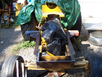
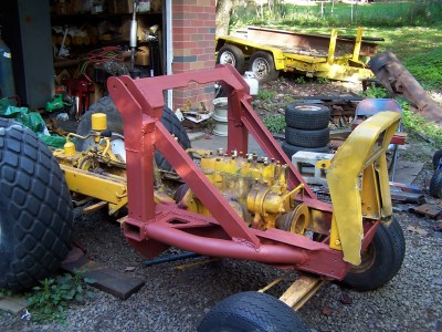
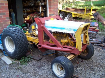
It's been long enough! If you are searching out hoses for your FEL project then it must be assembled enough to start posting pics!
(Curious minds want to know)

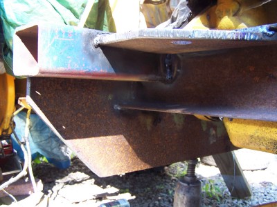
Landreo wrote:Keep the photos coming!. A 60 inch bucket may be too big depending on what you plan on loading. What are you going to do wiht the front axel and spindles, leave stock and wait for them to break or do you have other thoughts?
Landreo wrote:Keep the photos coming!. A 60 inch bucket may be too big depending on what you plan on loading. What are you going to do wiht the front axel and spindles, leave stock and wait for them to break or do you have other thoughts?
Return to “Lo-Boy Series - 154, 184, 185”
Users browsing this forum: No registered users and 1 guest


