Page 1 of 1
Manual Lift Assembly Diagram
Posted: Sat Jun 08, 2013 7:41 pm
by PVF1799
Our 48 FCUB does not have TC. I've looked through all the manuals I've printed and don't see a parts list for this assembly. What I am trying to locate is the original way the spring assist was attached at the back.
For years, we've had some piece of chain that's not original equipment. Could you kindly point me in the direction of the correct manual for this attachment?
Thanks.
Ken
Re: Manual Lift Assembly Diagram
Posted: Sat Jun 08, 2013 7:55 pm
by Barnyard
Here is the parts breakdown.

Here are a couple pix of mine.
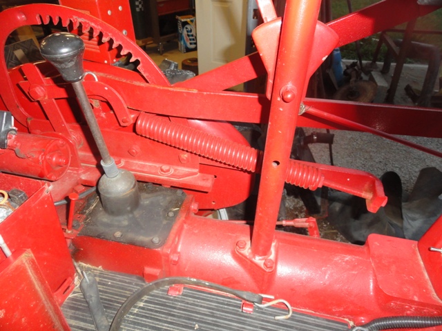
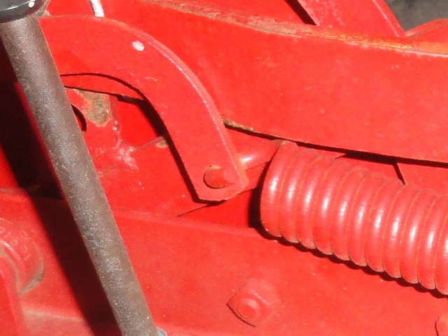
I have seen the spring loop mounted from the front and back on different tractors. I am not sure which is correct or if it matters.
Re: Manual Lift Assembly Diagram
Posted: Sat Jun 08, 2013 8:43 pm
by Arthur Luke
Barnyard beat me to it.
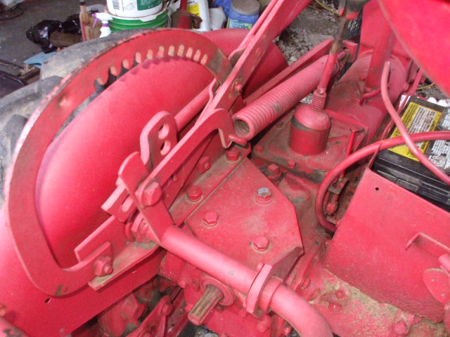
- Larry 1948 001.JPG (118.2 KiB) Viewed 1529 times
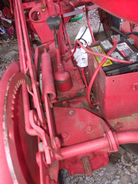
- Larry 1948 002.JPG (128.04 KiB) Viewed 1529 times
Re: Manual Lift Assembly Diagram
Posted: Sat Jun 08, 2013 8:58 pm
by PVF1799
Thanks Barnyard.
I am missing part #11 from the diagram. Spoke with Dad - he can't recall why this part is gone and replaced by a chain.
Ok-who's got one I can purchase or one they can template on cardboard, so I can make one.
All the help is much appreciated. BTW, Barnyard - what book is that diagram out of?
Ken
Re: Manual Lift Assembly Diagram
Posted: Sat Jun 08, 2013 9:06 pm
by Barnyard
Ken, it is on the manual server under "Cub Parts Manual". It is CBI-1A Revision 12 section 13 - "Common Units"
Re: Manual Lift Assembly Diagram
Posted: Mon Jun 10, 2013 5:21 pm
by Rudi
Ken:
Almost all of the Cub Implement Manuals will have a section on the Master Control Lever as well. Just a little trivia

Re: Manual Lift Assembly Diagram
Posted: Mon Jun 10, 2013 9:14 pm
by 48Beacon
Ken, If you are missing part #11 you will need #10 as well. Part # 11 to my manual lift was very worn. I had a machinist weld a bushing into my part #11. It is not free flowing like it was in its original design, but so far it works. Mike
Re: Manual Lift Assembly Diagram
Posted: Mon Jun 10, 2013 9:25 pm
by PVF1799
Thanks, I'll check it when it's disassembled. Right now the original bolt is still through part #10, except a chain link is where #11 would be bolted.
I'll need someone to template #11 for me so I can make one - unless one of ya'll has one for sale.
Ken