Page 1 of 2
49' cub wiring schematic
Posted: Thu May 10, 2007 8:13 am
by flag
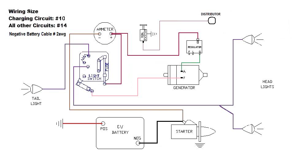
This is a schematic I made from a template of the only close wiring diagram to my 6v system and a couple noticeable differences and was wondering if some one could tell me if I need to modify it.
1. On the amp meter picture I made a boo boo indicating the + & - lable wrong but it is how it is wired.
2. Colors in chart are not the actual colors.
3. The voltage regulator field & load are not connect to anything.
4. The head & tail lights are reversed on the light switch post connections.
5. There are no fuses except on light switch.
This is the way it was when I got it, meaning that it could be wrong

Any ideas anybody

Posted: Thu May 10, 2007 8:38 am
by TexCub
Just as a point of comparison, I'll check my wiring to your diagram this afternoon and maybe add a schematic of my wiring. I just replaced the wiring as it was on my '53 Cub. I don't think my wiring matched any of the diagrams floating around here or in the manuals. I've got the rationale for the wiring down in theory, but I'm pretty green when it comes to this topic...
Posted: Thu May 10, 2007 9:17 am
by Eugene
http://ihregistry.com/wiring/master.html
Section K has a number of wiring diagrams for the Cub. Print out sections K2, K3 and K4. Many of the diagrams are close but not exactly identical to what is currently on any given Cub.
I didn't fully check out your diagram. The generator/regulator appears to be wired incorrectly. The F wire on the generator goes to the regulator.
In your diagram the ignition switch is correctly wired for a magneto.
Eugene
Posted: Thu May 10, 2007 10:36 am
by flag
Eugene K2 is close to mine and that is where I found the chart that I made mine from, thanks. The light switch if different too!
Posted: Thu May 10, 2007 11:01 am
by Donny M
Looks to me that what you have labeled as distributor should be labeled mag. The mag is grounded through the switch, not the distributor.
Here are a couple of schematics that are correct.
Mag early wiring:

You can see that the mag wiring is completely independant from the starting/charging wiring.
Later wiring with a distributor:


Posted: Thu May 10, 2007 4:54 pm
by John *.?-!.* cub owner
It appears to me that someone has installed a voltage regulator, but is only using it for a cutout. I have never seen this done before, but I assume it will work. Since it has a regulator on it, I would remove the connection between the F term of the gen and the light switch and replace it with one from the F term of regulator to F term of generator. Then the regulator will control the chrge rate instead of the light switch controlling it.
Posted: Thu May 10, 2007 9:16 pm
by flag
Donny M, you are right...I meant the mag and thanks for the diagram.
John *.?-!.*, I will change it as you described. Thanks a mil.
Today I took the negative term off and use a digital volt meter and measure the output from the positive terminal of the battery and the negative cable and it was 13.6v-14.0v.
I thought it would be 6v?
Posted: Fri May 11, 2007 1:37 am
by deputy jailer
John
Thats what I done and my generator/regulator. It seemed to work a lot better than through the switch. Either would work though

Posted: Fri May 11, 2007 6:22 am
by flag
What happens when you leave the switch on, does it over charge battery

Posted: Fri May 11, 2007 6:50 am
by Bigdog
Left in the high charge position, you can over-charge the battery but it would have to be used long and hard daily in order to do that. Mowing for a few hours every week would do no harm.
Posted: Fri May 11, 2007 7:45 am
by John *.?-!.* cub owner
flag wrote:What happens when you leave the switch on, does it over charge battery
If you make the change I suggested, leaving the light switch in the hi position will have no effect, the F lead is what it uses to control the charge.
It sounds as if you may have a 12 volt battery in it. I have seen that done a few times, and some 6 volt generators are capable of charging a 12 volt battery, but slowly. is the regulator marked for 6 volts, or for 12 volts?
Posted: Fri May 11, 2007 9:25 am
by Rudi
Guys:
Need a hand.. and maybe a quick suggestion.
Donny linked to this schematic:
Bob Melville's schematic:

is somewhat similar to what we have on Alde's Cub. What are the differences.. and how do I PROPERLY wire Alde's Cub.
He has the 10SI, IC-10 external coil for use with an external ballast resistor, the external ballast resistor, lights etc.... but no fuse. I gotta go get a fuse and fuse holder.. which fuse holder do I need.
Now.. what would be really useful is a combination of these two schematics for a Cub with mostly a standard installation but with the 10si and the external ballast resistor.
Posted: Fri May 11, 2007 11:10 am
by flag
Thanks Bigdog, good to know this because that is what I have been doing! only a couple hours every now and then I use it.
John *.?-!.* it is a 6v battery, not sure how to tell if it is a 12v regulator though.
I am going to make the change you suggested.
The amp meter was showing charge when I put cub back together and after working in the garden for 1 hour I noticed the meter not registering charge. I noticed the middle cell of battery had trickled some electrolite out.
Thats when I checked the volts between positive side of battery and the negative cable to see if generator was putting out and it was between 13v-14v.
The cub was wired back up as it was originally. I had never checked the volts before so it may have been doing this all along. I have put several batteries in it over 4yr period (did it burn them out). So I was wandering if it was wired wrong when I got it or like you say...could it be a 12v regulator and if so, would that change the voltage to the battery?
Also can just the amp needle be defecftive and pass voltage through?
Thanks for all ya'll input helping to get this cub right!
Posted: Fri May 11, 2007 11:24 am
by Bigdog
Sounds like you are definitely overcharging the battery. Find a 6 volt regulator and then re-wire the circuit and it should cure the problem. To answer your question about the ammeter - yes it is possible for the guage to not read at all and it will still pass current since it is a shunt type meter.
Posted: Fri May 11, 2007 6:07 pm
by flag
Sounds like good advise... I'll get it and change wiring and then post the results.